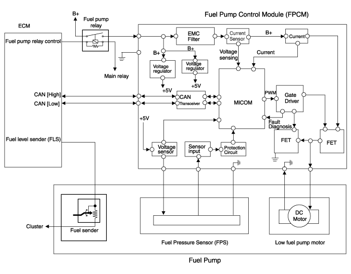
Hyundai Sonata LF: Fuel Delivery System / Fuel Pump Control Module (FPCM) Schematic Diagrams
Hyundai Sonata LF 2014-2019 Service Manual / Engine Control / Fuel System / Fuel Delivery System / Fuel Pump Control Module (FPCM) Schematic Diagrams
| Circuit Diagram |

| Fuel Pressure Control Module (FPCM) Terminal And Input/Output signal |

FPCM Terminal Function
| Pin No. | Description | Connected to |
| 1 | Fuel sender ground | Fuel Pump |
| 2 | Fuel pressure sensor (FPS) signal input | Fuel Pressure Sensor (FPS) |
| 3 | CAN [High] | ?ECM |
| 4 | Fuel pressure sensor (FPS) power supply (+5V) | Fuel Pressure Sensor (FPS) |
| 5 | Fuel pressure sensor (FPS) ground (-) | Fuel Pressure Sensor (FPS) |
| 6 | Fuel sender signal | Fuel Pump |
| 7 | - | - |
| 8 | CAN [Low] | ECM |
| 9 | Ground | Chassis Ground |
| 10 | Battery power (B+) | Fuel Pump Relay |
 Fuel Pump Control Module (FPCM) Specifications
Specification ItemsSpecificationApplied Voltate (V)6~18Current Consumption (A)Max. 15Fuel Pressure StartMax. 600 KPa (Max. 6.1 kgf/cm?, Max. 87...
 Fuel Pump Control Module (FPCM) Repair procedures
Removal 1. Turn the ignition switch OFF and disconnect the battery negative (-) cable. 2. emove the rear seat cushion. ( Refer to Body - "Rear Seat Assembly") 3...
Other information:
Hyundai Sonata LF 2014-2019 Service Manual: Intake Air Temperature Sensor (IATS) Repair procedures
I..
Hyundai Sonata LF 2014-2019 Service Manual: Lane Departure Warning System (LDWS) Unit Repair procedures
Removal 1. Disconnect the negative (-) battery terminal. 2. Remove the LDWS unit cover (A). 3. Disconnect the LDWS unit connector (A). 4. Remove the LDWS unit after disengaging the mounting bracket (A). Installation 1. Align LDWS unit with windshield bracket using forward edge point (A)...
Categories
- Manuals Home
- Hyundai Sonata Owners Manual
- Hyundai Sonata Service Manual
- Brake System
- Transmission Gear Oil Repair procedures
- Engine Electrical System
- New on site
- Most important about car
Copyright В© 2026 www.hsonatalf.org
