Hyundai Sonata LF: Body Electrical System / Power Door Mirrors
Components and Components Location
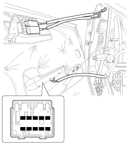
| Component Location |
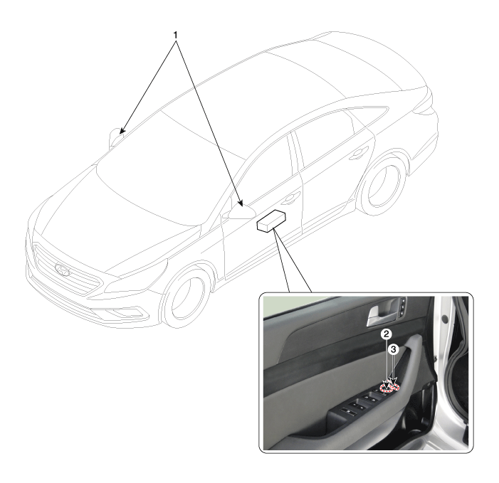
| 1. Power door mirror 2. Power door mirror switch | 3. Power folding mirror switch |
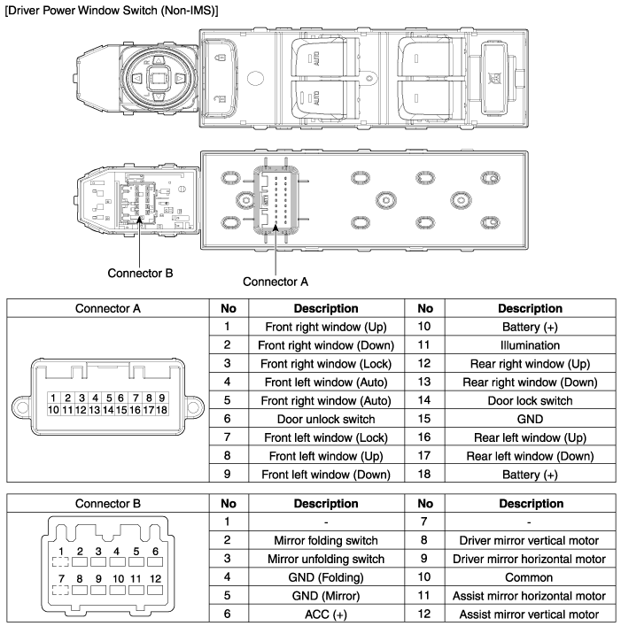
Power Door Mirror Switch Components and Components Location
| Components |

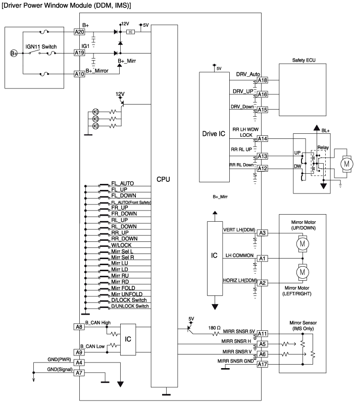
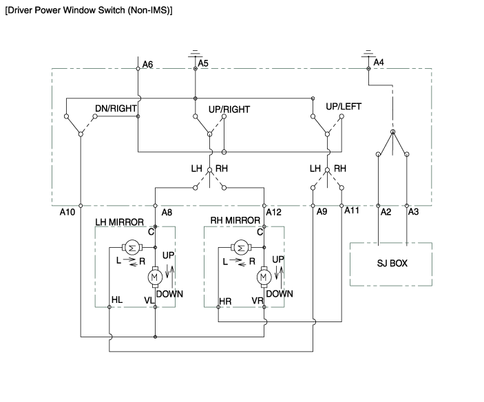
Power Door Mirror Switch Schematic Diagrams
| Circuit Diagram |
Power Door Mirror Switch Repair procedures
| Inspection |
| 1. |
Disconnect the negative (-) battery terminal. |
| 2. |
Remove the front left door trim.
(Refer to Body - "Front Door Trim") |
| 3. |
Disconnect the power mirror switch connector from the door trim.
|
| 4. |
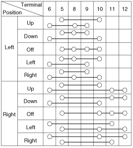
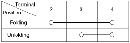
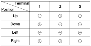
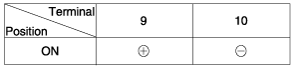
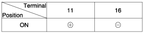
Check for continuity between the terminals in each switch position according to the table.
[Power Mirror Switch]
[Power Folding Mirror Switch]
|
| 1. |
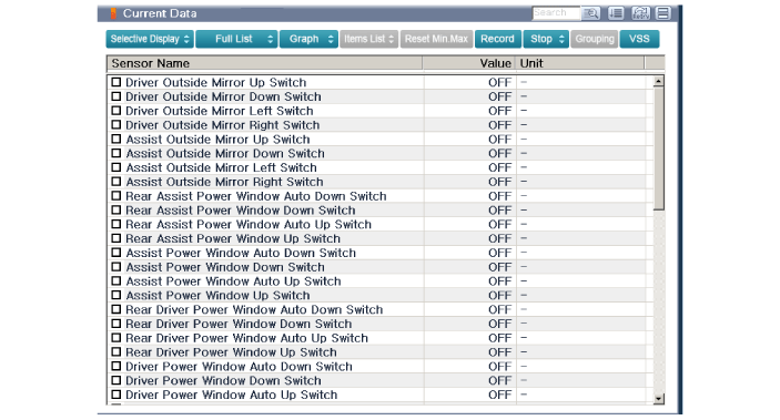
The body electrocal system can be quickly diagnosed failed parts with vehicle diagnostic system (GDS).
The diagnostic system (GDS) provides the following information.
|
| 2. |
Select the "Car Model" and the system to be checked in order to check the vehicle with the tester. |
| 3. |
Select the "Body Control Module (BCM)" to check the driver seat or assistant door module (DDM/ADM). |
| 4. |
Select the "Current Data" menu to search the current state of the input/output data.
The input/output data for the sensors corresponding to the driver seat or assistant door module(DDM/ADM) can be checked.
|
| 5. |
If you will check the power door lock operation forcefully, select "Actuation Test". |
| Removal |
|

| 1. |
Disconnect the negative (-) battery terminal. |
| 2. |
Remove the front door trim.
(Refer to Body - "Front Door Trim") |
| 3. |
Remove the power window switch assembly after disengaging the mounting clips.
|

| 1. |
Disconnect the negative (-) battery terminal. |
| 2. |
Remove the front door trim.
(Refer to Body - "Front Door Trim") |
| 3. |
Remove the power window switch assembly after disengaging the mounting clips.
|
| Installation |
| 1. |
Install the power window switch assembly. |
| 2. |
Install the front door trim after connect the connector. |
| 3. |
Connect the negative (-) battery terminal. |
Power Door Mirror Actuator Components and Components Location
| Components |
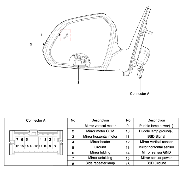
| 1. BSD Indicator 2. Side repeater lamp | 3. Puddle lamp |
Power Door Mirror Actuator Repair procedures
| Inspection |
| 1. |
Disconnect the negative (-) battery terminal. |
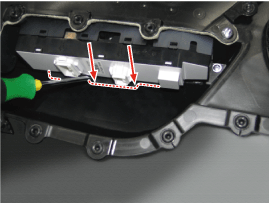
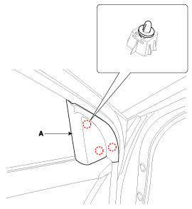
| 2. |
Remove the front door quadrant inner cover (A).
|
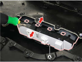
| 3. |
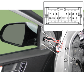
Disconnect the power door mirror connector from the harness.
|

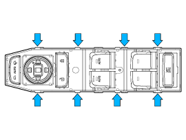
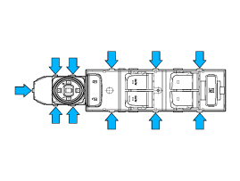
| 4. |
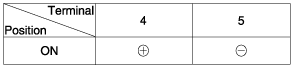
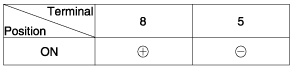
Apply battery voltage to each terminal as shown in the table and verify that the mirror operates properly.
[Mirror Control (LH/RT)]
[Puddle Lamp]
[BSD Indicator]
[Mirror Heater]
[Side Repeater Lamp]
|
| 1. |
The body electrocal system can be quickly diagnosed failed parts with vehicle diagnostic system (GDS).
The diagnostic system (GDS) provides the following information.
|
| 2. |
Select the "Car Model' and the system to be checked in order to check the vehicle with the tester. |
| 3. |
Select the "Body Control Module (BCM)" to check the driver seat or assistant door module (DDM/ADM). |
| 4. |
Select the "Current Data" menu to search the current state of the input/output data.
The input/output data for the sensors corresponding to the driver seat or assistant door module(DDM/ADM) can be checked.
|
| 5. |
If you will check the power door lock operation forcefully, select "Actuation Test". |
 Power Door Locks
Components and Components Location Component Location 1. DDM (Driver Door Module)2. ADM (Assist Door Module)3. SJB (Smart Junction Block)4. Door lock knob5...

Other information:
Hyundai Sonata LF 2014-2019 Service Manual: Water pump Troubleshooting
Troubleshooting SymptomsPossible CausesRemedyCoolant leakage • From the bleed hole of the water pump Visually check • Check leaks after about ten-minute warming up. • If coolant still leaks, replace a water pump. • If leakage stops, reuse the water pump (Do not replace the pump with a new one)...
Hyundai Sonata LF 2014-2019 Service Manual: Engine Coolant Temperature Sensor (ECTS) Description and Operation
Description Engine Coolant Temperature Sensor (ECTS) is located in the engine coolant passage of the cylinder head for detecting the engine coolant temperature. The ECTS uses a thermistor that changes resistance with the temperature. The electrical resistance of the ECTS decreases as the temperature increases, and increases as the temperature decreases...
Categories
- Manuals Home
- Hyundai Sonata Owners Manual
- Hyundai Sonata Service Manual
- Body Electrical System
- Brake System
- Timing System
- New on site
- Most important about car
