Hyundai Sonata LF: Engine Control System / Injector Troubleshooting
Hyundai Sonata LF 2014-2019 Service Manual / Engine Control / Fuel System / Engine Control System / Injector Troubleshooting
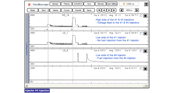
| Signal Waveform |
The three waveforms below are taken from the #1 and #4
injectors. The top waveform is from the high side (feed side) of the #1
and #4 injectors, while the middle waveform is from the low side (ground
side) of the #1 injector and the bottom waveform is from the low side
of the #4 injector.
The middle waveform is the same as the top waveform because
there is no ground for the circuit. With no current flowing in the
circuit, the #1 injector is not energized and fuel does not flow.
The bottom waveform shows that ground is supplied and there
is a voltage drop across the #4 injector. With current flowing in the
circuit, the #4 injector is energized and fuel flows.


Other information:
Hyundai Sonata LF 2014-2019 Service Manual: Knock Sensor (KS) Specifications
S..
Hyundai Sonata LF 2014-2019 Service Manual: Water Pipe Repair procedures
Removal and Installation 1. Remove the water temperature control assembly. (Refer to Colling System - "Water Temperature Control Assembly") 2. Remove the water pipe (A). Tightening torque M6 bolt and nuts : 9.8 ~ 11.8N.m (1.0 ~ 1.2kgf...
Categories
- Manuals Home
- Hyundai Sonata Owners Manual
- Hyundai Sonata Service Manual
- Engine Control System
- Engine Control / Fuel System
- Timing System
- New on site
- Most important about car

Copyright © 2026 www.hsonatalf.org