
Hyundai Sonata LF: Cooling System / Cooling Fan Repair procedures
Hyundai Sonata LF 2014-2019 Service Manual / Engine Mechanical System / Cooling System / Cooling Fan Repair procedures
| Removal and Installation |
Cooling Fan Assembly
| 1. |
Disconnect the battery terminals. |
| 2. |
Remove the under cover.
(Refer to Engine And Transaxle Assembly - "Engine Room Under Cover") |
| 3. |
Disconnect the air duct(A).
|
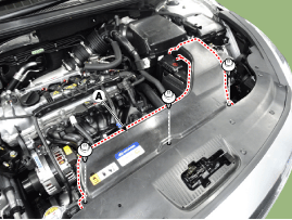
| 4. |
Disconnect the coolingfan connector(A).
|
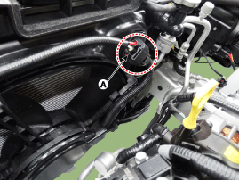
| 5. |
Disconnect the vacuum hose(A).
|
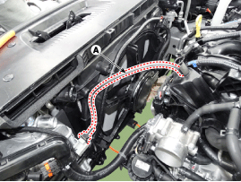
| 6. |
Remove the front bumper cover. (Refer to Body - "Front Bumper Cover") |
| 7. |
Remove the intake shield(A).
|
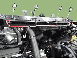
| 8. |
Loosen the mounting bolts and then remove the cooling fan(A).
|
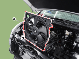
| 9. |
Install in the reverse order of removal. |
Resistor
| 1. |
Disconnect the coolingfan connector(A).
|
| 2. |
Remove the resistor (A) from the cooling fan shroud.
|
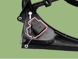
| 3. |
Install in the reverse order of removal. |
Disassembly
| 1. |
Remove the cooling fan (A) from the cooling fan assembly.
|
| 2. |
Remove the cooling fan motor cover(A).
|
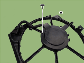
| 3. |
Remove the cooling fan motor(A).
|
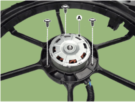
| 4. |
Install in the reverse order of removal. |
| Inspection |
Fan Motor
| 1. |
Disconnect the fan motor connector from the resistor. |
| 2. |
Connect the battery voltage to the "+" terminal and ground to " - " terminal. |
| 3. |
Check the cooling fan motor operates well. |


Other information:
Hyundai Sonata LF 2014-2019 Service Manual: In-car Sensor Description and Operation
Description The sensor contains a thermistor which measures the temperature of the inside. The signal decided by the resistance value which changes in accordance with perceived inside temperature, is delivered to heater control unit and according to this signal the control unit regulates incar temperature to intended value...
Hyundai Sonata LF 2014-2019 Service Manual: Components and Components Location
C..
Categories
- Manuals Home
- Hyundai Sonata Owners Manual
- Hyundai Sonata Service Manual
- Cooling System
- Body Electrical System
- Engine Control / Fuel System
- New on site
- Most important about car

Copyright В© 2026 www.hsonatalf.org