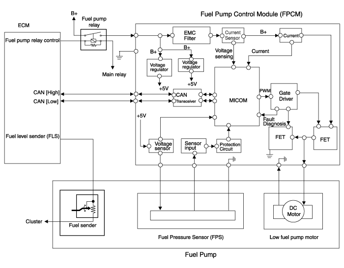
Hyundai Sonata LF: Fuel Delivery System / Fuel Pump Control Module (FPCM) Schematic Diagrams
| Circuit Diagram |

| Fuel Pressure Control Module (FPCM) Terminal And Input/Output signal |

| Pin No. | Description | Connected to |
| 1 | Fuel sender ground | Fuel Pump |
| 2 | Fuel pressure sensor (FPS) signal input | Fuel Pressure Sensor (FPS) |
| 3 | CAN [High] | ?ECM |
| 4 | Fuel pressure sensor (FPS) power supply (+5V) | Fuel Pressure Sensor (FPS) |
| 5 | Fuel pressure sensor (FPS) ground (-) | Fuel Pressure Sensor (FPS) |
| 6 | Fuel sender signal | Fuel Pump |
| 7 | - | - |
| 8 | CAN [Low] | ECM |
| 9 | Ground | Chassis Ground |
| 10 | Battery power (B+) | Fuel Pump Relay |
 Fuel Pump Control Module (FPCM) Specifications
Specification ItemsSpecificationApplied Voltate (V)6~18Current Consumption (A)Max. 15Fuel Pressure StartMax. 600 KPa (Max. 6.1 kgf/cm?, Max. 87...
 Fuel Pump Control Module (FPCM) Repair procedures
Removal 1. Turn the ignition switch OFF and disconnect the battery negative (-) cable. 2. emove the rear seat cushion. ( Refer to Body - "Rear Seat Assembly") 3...
Other information:
Hyundai Sonata LF 2014-2019 Service Manual: Starter Repair procedures
Removal 1. Disconnect the battery negative terminal. 2. Remove the battery tray. (Refer to Engine Electrical System - "Battery") 3. Remove the air duct and air cleaner assembly. (Refer to Engine Mechanical System - "Air Cleaner") 4...
Hyundai Sonata LF 2014-2019 Service Manual: Instrument Cluster Repair procedures
Removal • Put on gloves to protect your hands. • When prying with a flat-tip screwdriver, wrap it with protective tape, and apply protective tape around the related parts, to prevent damage. 1. Disconnect the negative (-) battery terminal...
Categories
- Manuals Home
- Hyundai Sonata Owners Manual
- Hyundai Sonata Service Manual
- Lighting System
- Intake And Exhaust System
- Engine Mechanical System
- New on site
- Most important about car
