
Hyundai Sonata LF: Cylinder Head Assembly / CVVT & Camshaft Description and Operation
Hyundai Sonata LF 2014-2019 Service Manual / Engine Mechanical System / Cylinder Head Assembly / CVVT & Camshaft Description and Operation
| Description |
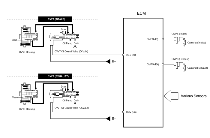
Continuous Variable Valve Timing (CVVT) system advances or
retards the valve timing of the intake and exhaust valve in accordance
with the ECM control signal which is calculated by the engine speed and
load.
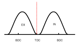
By controlling CVVT, the valve over-lap or under-lap occurs,
which makes better fuel economy and reduces exhaust gases (NOx, HC) and
improves engine performance through reduction of pumping loss, internal
EGR effect, improvement of combustion stability, improvement of
volumetric efficiency, and increase of expansion work.
This system consist of
| - |
the CVVT Oil Control Valve (OCV) which supplies the engine
oil to the cam phaser or runs out the engine oil from the cam phaser in
accordance with the ECM PWM (Pulse With Modulation) control signal, |
| - |
the CVVT Oil Temperature Sensor (OTS) which measures the engine oil temperature, |
| - |
and the Cam Phaser which varies the cam phase by using the hydraulic force of the engine oil. |
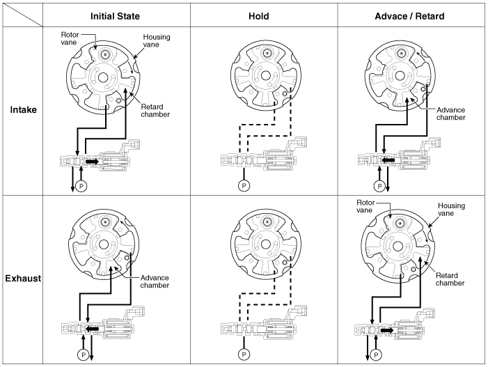
The engine oil getting out of the CVVT oil control valve
varies the cam phase in the direction (Intake Advance/Exhaust Retard) or
opposite direction (Intake Retard/Exhaust Advance) of the engine
rotation by rotating the rotor connected with the camshaft inside the
cam phaser.
| Operation Principle |
The CVVT has the mechanism rotating the rotor vane with
hydraulic force generated by the engine oil supplied to the advance or
retard chamber in accordance with the CVVT oil control valve control.
| [CVVT System Mode] |
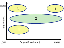
| (1) Low Speed / Low Load | (2) Part Load |
|
|
| (3) Low Speed / High Load | (4) High Speed / High Load |
|
|
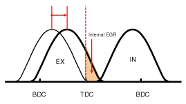

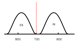
| Driving Condition | Exhaust Valve | Intake Valve | ||
| Valve Timing | Effect | Valve Timing | Effect | |
| (1) Low Speed /Low Load | Completely Advance | * Valve Under-lap * Improvement of combustion stability | Completely Retard | * Valve Under-lap * Improvement of combustion stability |
| (2) Part Load | Retard | * Increase of expansion work * Reduction of pumping loss * Reduction of HC | Retard | * Reduction of pumping loss |
| (3) Low Speed /High Load | Retard | * Increase of expansion work | Advance | * Prevention of intake back flow (Improvement of volumetric efficiency) |
| (4) High Speed /High Load | Advance | * Reduction of pumping loss | Retard | * Improvement of volumetric efficiency |

 CVVT & Camshaft Repair procedures
Removal 1. Remove the cylinder head cover. (Refer to Cylinder Head Assembly - "Cylinder Head Cover") 2. Turn the crankshaft damper pulley so that No...
Other information:
Hyundai Sonata LF 2014-2019 Service Manual: Tire Repair procedures
• Using tires and wheel other than the recommended sizes could cause unusual handling characteristics and poor vehicle control, resulting in a serious accident. Tire Wear 1. Measure the tread depth of the tires...
Hyundai Sonata LF 2014-2019 Service Manual: Center Pillar Trim Repair procedures
Replacement [Center Pillar Lower Trim] • Put on gloves to protect your hands. • When prying with a flat-tip screwdriver or use a prying trim tool, wrap it with protective tape, and apply protective tape around the related parts, to prevent damage...
Categories
- Manuals Home
- Hyundai Sonata Owners Manual
- Hyundai Sonata Service Manual
- Components and Components Location
- Steering System
- Suspension System
- New on site
- Most important about car

Copyright © 2026 www.hsonatalf.org