Hyundai Sonata: Brake System / Stop Signal Electronic Module Schematic Diagrams
Hyundai Sonata LF 2014-2019 Service Manual / Brake System / Brake System / Stop Signal Electronic Module Schematic Diagrams
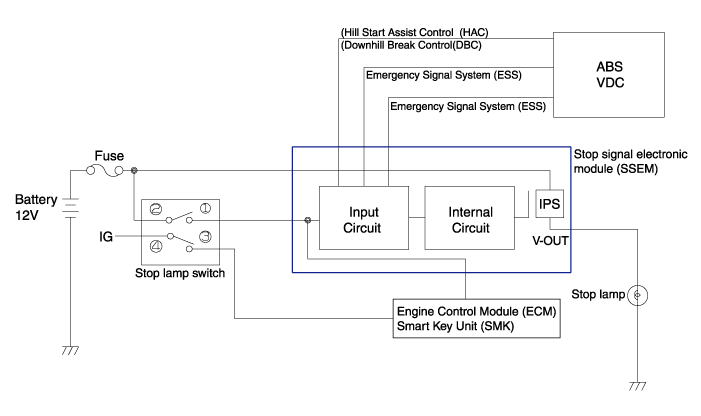
| System Circuit Diagram |
| Terminal Function |
| Teminal | Description |
| 1 | Ground |
| 2 | HAC/DBC Signal (Active Low) |
| 3 | ESS Signal (Active Low) |
| 4 | Stop lamp |
| 5 | Stop lamp switch |
| 6 | ECU/ SMK |
| 7 | ESS Signal (Active High) |
| 8 | Battery |
 Stop Signal Electronic Module Specifications
Specifications
CategoryDataOperation temperature range (°C)-40 ~ 85Preserving temperature range (°C)-40 ~ 105Operating voltage (V)5.8 ~ 16Rated current (A)15
...
 Stop Signal Electronic Module Repair procedures
Inspection
1. Fuse inspection
Mount the test fuse to the switch fuse and relay fuse part to confirm a normal joint fit.
2. Inspection of connector by each part
Check to see whether or not each c ...
Other information:
Hyundai Sonata LF 2014-2019 Owners Manual: To set Cruise Control speed
1. Push the CRUISE button on the steering wheel to turn the system on. The CRUISE
indicator will illuminate.
2. Accelerate to the desired speed, which must be more than 20 mph (30 km/h).
3. Push the toggle switch (1) down (SET-), and release it. The SET indicator
light will illuminate.
4. Releas ...
Hyundai Sonata LF 2014-2019 Service Manual: Specifications
Specification
ItemTypeBulb Watt (W)FrontA : HalogenB : HIDHead lamp (Halogen)Low beam/High beam(A Type)9005L+ /9005HL+66/60Low beam/High beam(B Type)D3S / Bi-Function35Front turn signal lamp 28/8W28/8Front turn signal lamp (B Type) LEDLEDDaytime Running Light (DRL)/ side marker light L ...
© 2018-2025 www.hsonatalf.org
