Hyundai Sonata LF: Brake System / Master Cylinder Repair procedures
Hyundai Sonata LF 2014-2019 Service Manual / Brake System / Brake System / Master Cylinder Repair procedures
| Removal |
| 1. |
Turn ignition switch OFF and disconnect the negative (-) battery cable. |
| 2. |
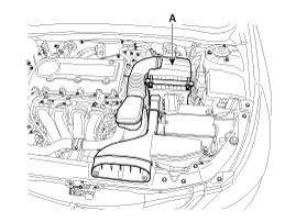
Remove the air cleaner assembly (A).
|
| 3. |
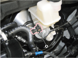
Disconnect the brake fluid level switch connector (A).
|
| 4. |
Remove the brake fluid from the master cylinder reservoir with a syringe.
|

| 5. |
Disconnect the brake tube (A) from the master cylinder by loosening the tube flare nut.
|

| 6. |
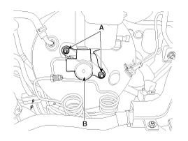
Remove the master cylinder (B) from the brake booster after loosening the mounting nuts (A).
|
| 7. |
Loosen the screw and then remove the reservior.
|
| Installation |
| 1. |
Installation is the reverse of removal. |
| 2. |
After installation, bleed the brake system.
(Refer to Brake System Bleeding - "Brake Sysem Bleeding")
(Refer to ESP (Electronic Stability Program System) - "ESP System Bleeding") |


Other information:
Hyundai Sonata LF 2014-2019 Service Manual: Interior Body Repair
Interior A * These dimensions indicated in this figure are actual-measurement dimensions. [ Unit : mm (inch) ] Interior B * These dimensions indicated in this figure are actual-measurement dimensions. [ Unit : mm (inch) ] Interior C * These dimensions indicated in this figure are actual-measurement dimensions...
Hyundai Sonata LF 2014-2019 Service Manual: Description and Operation
Description Block Diagram LDWS is Composed of Below Units NoItemFunctionPosition1LDWS UNIT 1. Lane Departure Warning System (LDWS) : Detects drive lane in front and engages warning function if the vehicle is in danger of departing from the drive lane...
Categories
- Manuals Home
- Hyundai Sonata Owners Manual
- Hyundai Sonata Service Manual
- Audio
- Transmission Gear Oil Repair procedures
- Front Driveshaft Repair procedures
- New on site
- Most important about car

Copyright © 2026 www.hsonatalf.org