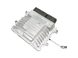
Hyundai Sonata LF: Dual Clutch Transmission Control System / DCT Control Module (TCM) Repair procedures
| Inspection |
| Transmission Control Module (TCM) Inspection Procedure |
| 1. |
Inspecting TCM ground circuit: Measure the resistance between the TCM and chassis ground.
(Check the terminal connected to the chassis ground while using the back of the harness connector as the base point for TCM.)
|
| 2. |
Inspecting the TCM connector: Disconnect the TCM connector
and visually inspect to see whether there is a bend on the ground
terminal of the harness connector. Also visually check the connection
pressure. |
| 3. |
If no problem is found during inspection in step 1 and step
2, then the problem is with the TCM itself. In this case, replace the
TCM and inspect the vehicle again. |
| 4. |
Re-inspecting TCM: Install the TCM that was determined to
have malfunctioned from step 3 in another vehicle. Reset the error code
and then check the operation in that vehicle. If the vehicle operates
without any problems, then inspect the first vehicle with the initial
problem again. |
| Removal |
| 1. |
Turn ignition switch OFF and disconnect the battery negative (-) terminal. |
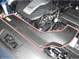
| 2. |
Remove the air duct (A).
|
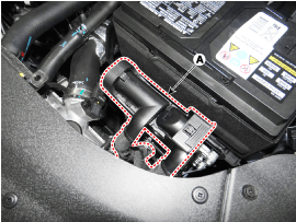
| 3. |
Disconnect the TCM connector (A).
|
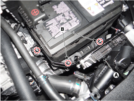
| 4. |
Remove the TCM (A) after removing the bracket mounting nut (B-3ea).
|
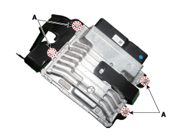
| 5. |
Remove the TCM from the bracket after loosening the bolt (A-4ea).
|
| Installation |
| 1. |
Install in the reverse order of removal.
|

 DCT Control Module (TCM) Schematic Diagrams
1. TCM Connector and Terminal Function 2. TCM Terminal Function Connector [A] PinDescriptionPinDescription1Clutch Actuator (Clutch Motor 1 (ODD)_Phase V)17-2Clutch actuator (Clutch Motor 2 (EVEN) Phase V)18Clutch Actuator (Clutch Motor 1 (ODD)_HALL 1)3Select Actuator (Shift Solenoid 2 (EVEN)_Ground)19Clutch Actuator (Clutch Motor 1 (ODD)_Supply)4Select Actuator (Shift Solenoid 1 (ODD) Push)20Select Actuator (Shift Solenoid 1 (ODD)_Sensor Supply)5Clutch Actuator (Clutch Motor 1 (ODD)_Phase U)21Select Actuator (Shift Solenoid 2 (EVEN)_Sensor Supply)6Clutch Actuator (Clutch Motor 2 (EVEN)_Phase U)22Select Actuator (Shift Solenoid 2 (EVEN)_Sensor Ouput)7Select Actuator (Shift Solenoid 1 (ODD)_Ground)23Clutch Actuator (Clutch Motor 2 (EVEN)_HALL 2)8Select Actuator (Shift Solenoid 2 (EVEN)_ Pull)24Clutch Actuator (Clutch Motor 2 (EVEN)_HALL 3)9Clutch Actuator (Clutch Motor1 (ODD)_Phase W)25Clutch Actuator (Clutch Motor 2 (EVEN)_Ground)10Clutch Actuator (Clutch Motor 2 (EVEN)_Phase W)26Select Actuator (Shift Solenoid 1 (ODD)_Sensor Output)11Select Actuator (Shift Solenoid 1 (ODD) Pull)27-12Select Actuator (Shift Solenoid 2 (EVEN) Push)28Clutch Actuator (Clutch Motor 2 (EVEN)_HALL 1)13Clutch Actuator (Clutch Motor 1 (ODD)_HALL 2)29Clutch Actuator (Clutch Motor 2 (EVEN)_Supply)14Clutch Actuator (Clutch Motor (ODD)_HALL 3)30Select Actuator (Select Solenoid 1 (ODD)_Sensor Ground)15Clutch Actuator (Clutch Motor 1 (ODD)_Ground)31Select Actuator (Select Solenoid 2 (EVEN)_Sensor Ground)16-32- Connector [B] PinDescriptionPinDescription1-35-2-36-3ON / START Input37-4Paddle Shift (Up) Switch signal38-5Inhibitor Switch "P" Input signal39-6Inhibitor Switch "R" Input signal40-7Inhibitor Switch "D" Input signal41Shift Actuator (Shift Motor 2 (EVEN) _HALL 2)8Sports mode "Down" shift42Shift Actuator (Shift Motor 2 (EVEN) _HALL 3)9Clutch Speed Sensor (EVEN) Ground43Inhibitor Switch "M" Input signal10-44CAN1 Communication Port1 High11-45CAN1 Communication Port1 Low12-46-13Shift Actuator (Shift Motor 1 (ODD) _HALL 2)47-14Shift Actuator (Shift Motor 1 (ODD) _HALL 3)48Flex ray High (BP)15-49Input Speed Supply 1 (ODD)16-50Input Speed Signal 1 (ODD)17Battery Power Low VBD 51-18Paddle Shift Down signal52-19Shift Lever Select Switch53-20Inhibitor Switch "N" Input signal54Shift Actuator (Shift Motor 2 (EVEN) _Supply)21Sports mode "Up" shift55Shift Actuator (Shift Motor 2 (EVEN) _HALL 1)22-56Shift Actuator (Shift Motor 2 (EVEN) _Sensor Ground)23Input Speed Supply 2 (EVEN)57Power Ground 1 for High Current Modules245V spare supply output58Power Ground 2 for High Current Modules25-59Shift Actuator (Shift Motor 2 (EVEN)_Phase W)26Shift Solenoid 1 Position Sensor Output60Shift Actuator (Shift Motor 1 (ODD)_Phase W)27Select Actuator (Shift Motor 1 (ODD)_HALL 1)61 Power Ground 3 for High Current Modules28Select Actuator (Shift Motor 1 (ODD)_Sensor Ground)62-29-63Shift Actuator (Shift Motor 2 (EVEN)_Phase V)30CAN2 Communication Port2 High64Shift Actuator (Shift Motor 1 (ODD)_Phase V)31CAN2 Communication Port2 Low65Motor Supply Voltage 1 from Direct Battery32-66Motor Supply Voltage 2 from Direct Battery33-67Shift Actuator (Shift Motor 2 (EVEN)_Phase U)34Flex ray bus, BM68Shift Actuator (Shift Motor 1 (ODD)_Phase U) 3...

Other information:
Hyundai Sonata LF 2014-2019 Service Manual: Advanced Smart Cruise Control (ASCC) Switch Repair procedures
Inspection [Measuring Resistance] 1. Disconnect the smart cruise control switch connector from the control switch. 2. Measure resistance between terminals on the control switch when each function switch is ON (switch is depressed). Function switchTerminalResistanceSET -3 - 5550?±5%RES +3 - 5880?±5%CANCEL3 - 5330?±5%CRUISE3 - 51...
Hyundai Sonata LF 2014-2019 Service Manual: Rear Disc Brake Repair procedures
Removal [General Type] 1. Raise the vehicle, and make sure it is securely supported. 2. Remove the wheel cap(A). Be careful not to damage to the wheel cap(A) when removing the it. 3. Remove the front wheel and tire (A) from front hub...
Categories
- Manuals Home
- Hyundai Sonata Owners Manual
- Hyundai Sonata Service Manual
- Engine Mechanical System
- Emission Control System
- Engine Control / Fuel System
- New on site
- Most important about car
