Hyundai Sonata LF: Engine Control System / CVVT Oil Control Valve (OCV) Repair procedures
| 1. |
Turn the ignition switch OFF. |
| 2. |
Disconnect the OCV connector. |
| 3. |
Measure resistance between the OCV terminals 1 and 2. |
| 4. |
Check that the resistance is within the specification.
Specification: Refer to “Specification”
|
|
| 1. |
Turn the ignition switch OFF and disconnect the battery negative (-) cable. |
| 2. |
Disconnect the CVVT oil control valve connector (A). |
| 3. |
Remove the installation bolt (B), and then remove the valve from the engine.
[Bank 1 / Intake] 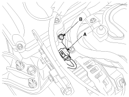
[Bank 1 / Exhaust] 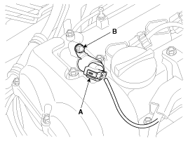
|
| • |
Install the component with the specified torques. |
| • |
Note that internal damage may occur when the component is dropped. If the component has been dropped, inspect before installing. |
|
| • |
Apply engine oil to the valve O-ring.
|
|
| 1. |
Install in the reverse order of removal.
CVVT oil control valve installation bolt:
9.8 ~ 11.8 N.m (1.0 ~ 1.2 kgf.m, 7.2 ~ 8.7 lb-ft)
|
|
Desrcription
The Electric WGT Control Actuator is installed on the
turbocharger.It operates the vain in the Waste Gate Turbocharger (WGT)
and regulates the compressed air amount by the ECM's PWM signal...
Other information:
Removal
Engine removal is not required for this procedure.
•
Use fender covers to avoid damaging painted surfaces.
•
To avoid damaging the cylinder head, wait until the engine
coolant temperature drops below normal temperature before removing it...
C..


 Electric WGT Control Actuator Description and Operation