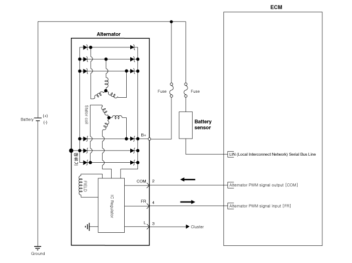
Hyundai Sonata LF: Charging System / Alternator Schematic Diagrams
Hyundai Sonata LF 2014-2019 Service Manual / Engine Electrical System / Charging System / Alternator Schematic Diagrams
| Circuit Diagram |

|
 Alternator Components and Components Location
Components 1. OAD (Overrunning Alternator Decoupler) 2. Front Bracket3. Front Bearing4. Stator5. Rotor6. Rear Bearing7. Rear Bracket8. Brush Holder Assembly9...
 Alternator Repair procedures
Removal 1. Disconnect the battery negative terminal. 2. Loosen the mounting bolts (A) and then, turn the adjusting bolt (B) clockwise to loosen tension...
Other information:
Hyundai Sonata LF 2014-2019 Service Manual: Stop Signal Electronic Module Components and Components Location
C..
Hyundai Sonata LF 2014-2019 Service Manual: TPMS Receiver Repair procedures
Replacement 1. Disconnect the negative (-) battery cable. 2. Remove the glove box. (Refer to Body - "Crash Pad") 3. Remove faulty part and fit bracket assembly to new part. 4. Secure new part to vehicle and fit connector. 5. Re-connect battery and turn Ignition on...
Categories
- Manuals Home
- Hyundai Sonata Owners Manual
- Hyundai Sonata Service Manual
- Engine Control System
- Lighting System
- Engine Control / Fuel System
- New on site
- Most important about car
Copyright © 2026 www.hsonatalf.org

