Hyundai Sonata LF: Fuel Delivery System / Accelerator Pedal Repair procedures
Hyundai Sonata LF 2014-2019 Service Manual / Engine Control / Fuel System / Fuel Delivery System / Accelerator Pedal Repair procedures
| Removal |
| 1. |
Turn the ignition switch OFF and disconnect the negative (-) battery cable. |
| 2. |
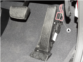
Disconnect the accelerator position sensor connector (A).
|
| 3. |
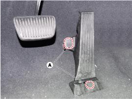
Remove the mounting cap (A).
|
| 4. |
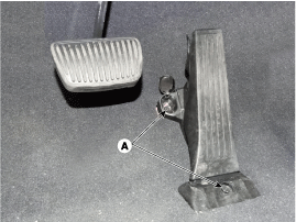
Remove the installation bolt (A), and then remove the accelerator pedal module.
|
| Installation |
| 1. |
Install in the reverse order of removal.
|
 Filler-Neck Assembly Repair procedures
Removal 1. Turn the ignition seitch OFF and disconnect the battery negative (-) cable. 2. Open the fuel filler door and then remove the filler-neck installation screw (A)...
 Delivery Pipe Repair procedures
Removal In case of removing the high pressure fuel pump, high pressure fuel pipe, delivery pipe, and injector, there may be injury caused by leakage of the high pressure fuel...
Other information:
Hyundai Sonata LF 2014-2019 Service Manual: Smart Key Unit Components and Components Location
C..
Hyundai Sonata LF 2014-2019 Service Manual: Rear Combination Lamp Repair procedures
Removal 1. Disconnect the negative (-) battery terminal. 2. Loose the nuts (4EA) holding the rear combination lamp then disconnect the connector (A) then remove the outside rear combination lamp assembly. 3. Remove the bulb (A) after turnicng in the counter clock-wise direction...
Categories
- Manuals Home
- Hyundai Sonata Owners Manual
- Hyundai Sonata Service Manual
- Brake System
- Engine Control / Fuel System
- Cooling System
- New on site
- Most important about car
Copyright В© 2026 www.hsonatalf.org


