Hyundai Sonata LF: Windshield Deicer / Windshield Deicer Switch Repair procedures
| Inspection |
| 1. |
The body electrocal system can be quickly diagnosed failed parts with vehicle diagnostic system (GDS).
The diagnostic system (GDS) provides the following information.
|
| 2. |
Select the "Car Model" and the system to be checked in order to check the vehicle with the tester. |
| 3. |
Select the "Smart Junction Box (SJB)" to check the windshield deicer. |
| 4. |
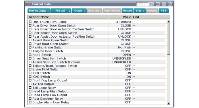
Select the "Current Date" menu to search the current state of the input/output data.
The input/output data for the sensors corresponding to the 'Smart Junction Box (SJB)' can be checked.
|
| 5. |
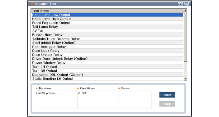
Select "Actuation Test", if you want to check the Smart Junction Box (SJB) data operation forcefully.
|
| Removal |
| 1. |
Disconnect the negative (-) battery terminal. |
| 2. |
Remove the heater and A/C controll unit.
(Refer to Heating, Ventilation, Air conditioning - "Heater & A/C Control Unit (Dual)") |
| Installation |
| 1. |
Install the heater and A/C control unit. |
| 2. |
Connect the negative (-) battery terminal. |
 Windshield Deicer Repair procedures
Inspection 1. Remove the cowl top cover. (Refer to Body - "Cowl Top Cover") 2. Disconnect the windshield deicer connector (A). 3. Check for continuity between the terminals of deicer lines...
Other information:
Hyundai Sonata LF 2014-2019 Service Manual: Master Cylinder Repair procedures
Removal 1. Turn ignition switch OFF and disconnect the negative (-) battery cable. 2. Remove the air cleaner assembly (A). 3. Disconnect the brake fluid level switch connector (A). 4. Remove the brake fluid from the master cylinder reservoir with a syringe...
Hyundai Sonata LF 2014-2019 Service Manual: Curtain Airbag (CAB) Module Repair procedures
Removal 1. Disconnect the battery negative cable and wait for at least 3 minutes before beginning work. 2. Remove the roof trim. (Refer to Body - "Roof Trim Assembly") 3. Disconnect the curtain airbag harness connector. 4. After loosening the mounting bolts and nuts remove the curtain airbag...
Categories
- Manuals Home
- Hyundai Sonata Owners Manual
- Hyundai Sonata Service Manual
- Body Electrical System
- Brake System
- Starter Repair procedures
- New on site
- Most important about car


