Hyundai Sonata LF: Blower / Intake Actuator Repair procedures

Hyundai Sonata LF 2014-2019 Service Manual / Heating, Ventilation and Air Conditioning / Blower / Intake Actuator Repair procedures

Inspection
1.
Turn the ignition switch OFF.
2.
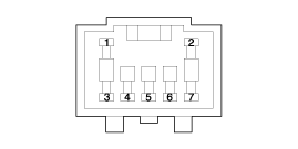
Disconnect the intake actuator connector.
3.
Verify that the intake actuator operates to the fresh position when connecting 12V to terminal 3 and grounding terminal 4.
Verify that the intake actuator operates to the recirculation position when connected in reverse.

1. -
2. -
3. Recirculated air
4. Sensor (+ 5V)
5. Feedback signal
6. Sensor ground
7. Fresh air

4.
Connect the intake actuator connector.
5.
Turn the ignition switch ON.
6.
Check the voltage between terminal 6 and 5.
Specification
Door position
Voltage (V)
Error detecting
Recirculated air
1.47
Low voltage : 0.1V or less
Fresh air
4
High voltage : 4.9V or more

It will feedback the current position of the actuator to controls.
7.
If the intake actuator does not operate well, substitute with a known-good intake actuator and check for proper operation.
8.
Replace the intake actuator if it is proved that there is a problem with it.
Diagnosis With GDS
1.
The heating, ventilation and air conditioning can be quickly diagnosed failed parts with vehicle diagnostic system (GDS).
? The diagnostic system (GDS) provides the following information.
(1) Self diagnosis: Checking the failure code (DTC) and display.
(2) Current data: Checking the system input/output data state.
(3) Actuation test: Checking the system operation condition.
(4) Additional function: Other controlling such as he system option and zero point adjustment.
2.
Select the 'Car model' and the system to be checked in order to check the vehicle with the tester.
3.
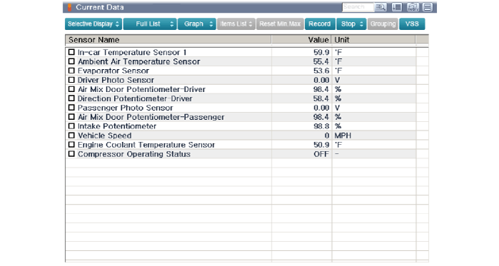
Select the 'Current data' menu to search the current state of the input/output data.
The input / output data for the sensors corresponding to the Intake Actuator can be checked.

4.
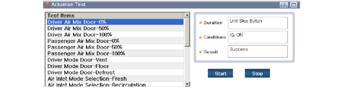
To perform compulsory operation on Intake Actuator input factors, select "ACTUATION TEST".

Replacement
1.
Disconnect the negative (-) battery terminal.
2.
Remove the glove box housing.
(Refer to Body - "Glove Box Housing")
3.
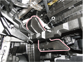
Remove the passenger's side shower duct (A) after loosening the screw.
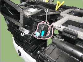
4.
Disconnect the connector (A) and then remove the intake actuator (B) after loosening the mounting screws.

5.
Install in the reverse order of removal.

    Intake Actuator Description and Operation

    Description The intake actuator is located at the blower unit. It regulates the intake door by a signal from the control unit. Pressing the intake selection switch will shift between recirculation and fresh air modes...

    Controller

    ..

    Other information:

    Hyundai Sonata LF 2014-2019 Service Manual: Seat Belt Buckle Switch (BS) Description and Operation


    Description The SRSCM shall monitor the status of the driver and front passenger seat belt buckle. The SRSCM provides one pin each for the driver and front passenger seat belt buckle status input. The seat belt buckle circuit operates from internal boost voltage supplied by the SRSCM, and uses chassis ground for the signal return...

    Hyundai Sonata LF 2014-2019 Service Manual: DCT Control Module (TCM) Schematic Diagrams


    1. TCM Connector and Terminal Function 2. TCM Terminal Function Connector [A] PinDescriptionPinDescription1Clutch Actuator (Clutch Motor 1 (ODD)_Phase V)17-2Clutch actuator (Clutch Motor 2 (EVEN) Phase V)18Clutch Actuator (Clutch Motor 1 (ODD)_HALL 1)3Select Actuator (Shift Solenoid 2 (EVEN)_Ground)19Clutch Actuator (Clutch Motor 1 (ODD)_Supply)4Select Actuator (Shift Solenoid 1 (ODD) Push)20Select Actuator (Shift Solenoid 1 (ODD)_Sensor Supply)5Clutch Actuator (Clutch Motor 1 (ODD)_Phase U)21Select Actuator (Shift Solenoid 2 (EVEN)_Sensor Supply)6Clutch Actuator (Clutch Motor 2 (EVEN)_Phase U)22Select Actuator (Shift Solenoid 2 (EVEN)_Sensor Ouput)7Select Actuator (Shift Solenoid 1 (ODD)_Ground)23Clutch Actuator (Clutch Motor 2 (EVEN)_HALL 2)8Select Actuator (Shift Solenoid 2 (EVEN)_ Pull)24Clutch Actuator (Clutch Motor 2 (EVEN)_HALL 3)9Clutch Actuator (Clutch Motor1 (ODD)_Phase W)25Clutch Actuator (Clutch Motor 2 (EVEN)_Ground)10Clutch Actuator (Clutch Motor 2 (EVEN)_Phase W)26Select Actuator (Shift Solenoid 1 (ODD)_Sensor Output)11Select Actuator (Shift Solenoid 1 (ODD) Pull)27-12Select Actuator (Shift Solenoid 2 (EVEN) Push)28Clutch Actuator (Clutch Motor 2 (EVEN)_HALL 1)13Clutch Actuator (Clutch Motor 1 (ODD)_HALL 2)29Clutch Actuator (Clutch Motor 2 (EVEN)_Supply)14Clutch Actuator (Clutch Motor (ODD)_HALL 3)30Select Actuator (Select Solenoid 1 (ODD)_Sensor Ground)15Clutch Actuator (Clutch Motor 1 (ODD)_Ground)31Select Actuator (Select Solenoid 2 (EVEN)_Sensor Ground)16-32- Connector [B] PinDescriptionPinDescription1-35-2-36-3ON / START Input37-4Paddle Shift (Up) Switch signal38-5Inhibitor Switch "P" Input signal39-6Inhibitor Switch "R" Input signal40-7Inhibitor Switch "D" Input signal41Shift Actuator (Shift Motor 2 (EVEN) _HALL 2)8Sports mode "Down" shift42Shift Actuator (Shift Motor 2 (EVEN) _HALL 3)9Clutch Speed Sensor (EVEN) Ground43Inhibitor Switch "M" Input signal10-44CAN1 Communication Port1 High11-45CAN1 Communication Port1 Low12-46-13Shift Actuator (Shift Motor 1 (ODD) _HALL 2)47-14Shift Actuator (Shift Motor 1 (ODD) _HALL 3)48Flex ray High (BP)15-49Input Speed Supply 1 (ODD)16-50Input Speed Signal 1 (ODD)17Battery Power Low VBD 51-18Paddle Shift Down signal52-19Shift Lever Select Switch53-20Inhibitor Switch "N" Input signal54Shift Actuator (Shift Motor 2 (EVEN) _Supply)21Sports mode "Up" shift55Shift Actuator (Shift Motor 2 (EVEN) _HALL 1)22-56Shift Actuator (Shift Motor 2 (EVEN) _Sensor Ground)23Input Speed Supply 2 (EVEN)57Power Ground 1 for High Current Modules245V spare supply output58Power Ground 2 for High Current Modules25-59Shift Actuator (Shift Motor 2 (EVEN)_Phase W)26Shift Solenoid 1 Position Sensor Output60Shift Actuator (Shift Motor 1 (ODD)_Phase W)27Select Actuator (Shift Motor 1 (ODD)_HALL 1)61 Power Ground 3 for High Current Modules28Select Actuator (Shift Motor 1 (ODD)_Sensor Ground)62-29-63Shift Actuator (Shift Motor 2 (EVEN)_Phase V)30CAN2 Communication Port2 High64Shift Actuator (Shift Motor 1 (ODD)_Phase V)31CAN2 Communication Port2 Low65Motor Supply Voltage 1 from Direct Battery32-66Motor Supply Voltage 2 from Direct Battery33-67Shift Actuator (Shift Motor 2 (EVEN)_Phase U)34Flex ray bus, BM68Shift Actuator (Shift Motor 1 (ODD)_Phase U) 3...

    Categories

    read more

     
    Copyright В© 2026 www.hsonatalf.org