Hyundai Sonata LF: Body Electrical System / Multifunction Switch

Hyundai Sonata LF 2014-2019 Service Manual / Body Electrical System / Multifunction Switch

Specifications

Specifications
Items
Specifications
Rated voltage
DC 12V
Operating temperature range
-22 ~ +176°F (-30°C ~ +80°C)
Rated load
Washer
Washer : 6A (Motor load)

Components and Components Location

Component

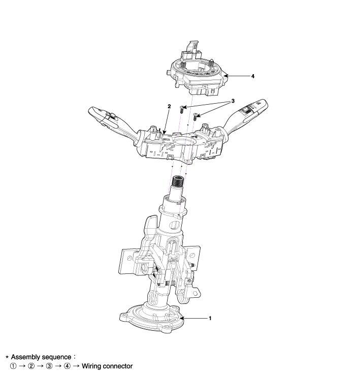
1. Steering column
2. Multifunction switch
3. Screw
4. Clock spring

Repair procedures

Removal
1.
Disconnect the negative (-) battery terminal.
2.
Remove the steering wheel.
(Refer to Steering System - "Steering Wheel")
3.
Remove the steering column upper and lower shrouds after loosening the screws.
(Refer to Body - "Steering Column Shroud Panal")
4.
Remove the clock spring.
(Refer to Restraint - "Driver Airbag (DAB) Module and Clock Spring")
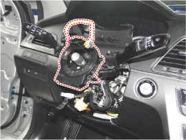
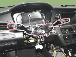
5.
Disconnect the multifunction switch connector (A).
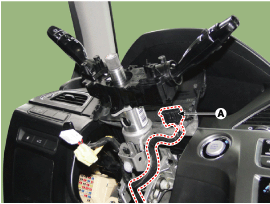
6.
Remove the multifunction switch assembly (A) after loosening the screws.

Installation
1.
Install the multifunction switch.
2.
Install the clock spring.
3.
Install the steering column upper and lower shrouds.
4.
Install the steering wheel.
Inspection
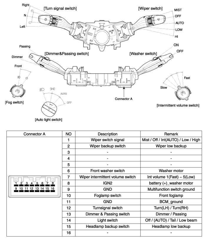
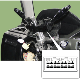
Multifunction Switch Inspection
1.
Check for continuity between the terminals in each switch position according to the table.

Switch
Switch Position
Switch Terminal
Resistance (?, ±3.5%)
Wiper switch
MIST
1-9
330
OFF
?
Intermittent (AUTO)
800
LOW
1800
HIGH
5700
Wiper intermittent volume
Volume 1
7-9
330
Volume 2
690
Volume 3
1310
Volume 4
2610
Volume 5
7310
Fog lamp switch
OFF
9-10
?
Front foglamp
910
Turnsignal switch
OFF
9-12
?
Left
910
Right
2910
Dimmer & Passing switch
OFF
9-13
?
Passing
910
Dimmer
2910
Light switgh
OFF
9-14
?
AUTO / DRL
680
Tail lamp
1680
Low beam
5580

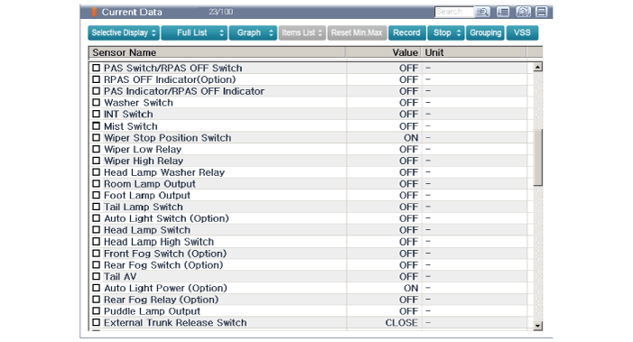
Inspection (with GDS)
1.
The body electrocal system can be quickly diagnosed failed parts with vehicle diagnostic system(GDS).
The diagnostic system(GDS) provides the following information.
(1)
Self diagnosis : Checking the failure code (DTC) and display
(2)
Current data : Checking the system input/output data state
(3)
Actuation test : Checking the system operation condition
(4)
Additional function : Other controlling such as he system option and zero point adjustment
2.
Select the "Car Model" and the system to be checked in order to check the vehicle with the tester.
3.
Select the "Body Control Module (BCM)" to check the multi function switch.
4.
Select the "Current Data" menu to search the current state of the input/output data.
The input/output data for the sensors corresponding to the multi function switch can be checked.

    Special Service Tools

    S..

    Horn

    Components and Components Location Component Location 1. Horn switch2. Horn relay (Built - in Metal Core Block PCB)3. Horn (Low pitch)4. Horn (High pitch)5...

    Other information:

    Hyundai Sonata LF 2014-2019 Service Manual: DCT Control Module (TCM) Schematic Diagrams


    1. TCM Connector and Terminal Function 2. TCM Terminal Function Connector [A] PinDescriptionPinDescription1Clutch Actuator (Clutch Motor 1 (ODD)_Phase V)17-2Clutch actuator (Clutch Motor 2 (EVEN) Phase V)18Clutch Actuator (Clutch Motor 1 (ODD)_HALL 1)3Select Actuator (Shift Solenoid 2 (EVEN)_Ground)19Clutch Actuator (Clutch Motor 1 (ODD)_Supply)4Select Actuator (Shift Solenoid 1 (ODD) Push)20Select Actuator (Shift Solenoid 1 (ODD)_Sensor Supply)5Clutch Actuator (Clutch Motor 1 (ODD)_Phase U)21Select Actuator (Shift Solenoid 2 (EVEN)_Sensor Supply)6Clutch Actuator (Clutch Motor 2 (EVEN)_Phase U)22Select Actuator (Shift Solenoid 2 (EVEN)_Sensor Ouput)7Select Actuator (Shift Solenoid 1 (ODD)_Ground)23Clutch Actuator (Clutch Motor 2 (EVEN)_HALL 2)8Select Actuator (Shift Solenoid 2 (EVEN)_ Pull)24Clutch Actuator (Clutch Motor 2 (EVEN)_HALL 3)9Clutch Actuator (Clutch Motor1 (ODD)_Phase W)25Clutch Actuator (Clutch Motor 2 (EVEN)_Ground)10Clutch Actuator (Clutch Motor 2 (EVEN)_Phase W)26Select Actuator (Shift Solenoid 1 (ODD)_Sensor Output)11Select Actuator (Shift Solenoid 1 (ODD) Pull)27-12Select Actuator (Shift Solenoid 2 (EVEN) Push)28Clutch Actuator (Clutch Motor 2 (EVEN)_HALL 1)13Clutch Actuator (Clutch Motor 1 (ODD)_HALL 2)29Clutch Actuator (Clutch Motor 2 (EVEN)_Supply)14Clutch Actuator (Clutch Motor (ODD)_HALL 3)30Select Actuator (Select Solenoid 1 (ODD)_Sensor Ground)15Clutch Actuator (Clutch Motor 1 (ODD)_Ground)31Select Actuator (Select Solenoid 2 (EVEN)_Sensor Ground)16-32- Connector [B] PinDescriptionPinDescription1-35-2-36-3ON / START Input37-4Paddle Shift (Up) Switch signal38-5Inhibitor Switch "P" Input signal39-6Inhibitor Switch "R" Input signal40-7Inhibitor Switch "D" Input signal41Shift Actuator (Shift Motor 2 (EVEN) _HALL 2)8Sports mode "Down" shift42Shift Actuator (Shift Motor 2 (EVEN) _HALL 3)9Clutch Speed Sensor (EVEN) Ground43Inhibitor Switch "M" Input signal10-44CAN1 Communication Port1 High11-45CAN1 Communication Port1 Low12-46-13Shift Actuator (Shift Motor 1 (ODD) _HALL 2)47-14Shift Actuator (Shift Motor 1 (ODD) _HALL 3)48Flex ray High (BP)15-49Input Speed Supply 1 (ODD)16-50Input Speed Signal 1 (ODD)17Battery Power Low VBD 51-18Paddle Shift Down signal52-19Shift Lever Select Switch53-20Inhibitor Switch "N" Input signal54Shift Actuator (Shift Motor 2 (EVEN) _Supply)21Sports mode "Up" shift55Shift Actuator (Shift Motor 2 (EVEN) _HALL 1)22-56Shift Actuator (Shift Motor 2 (EVEN) _Sensor Ground)23Input Speed Supply 2 (EVEN)57Power Ground 1 for High Current Modules245V spare supply output58Power Ground 2 for High Current Modules25-59Shift Actuator (Shift Motor 2 (EVEN)_Phase W)26Shift Solenoid 1 Position Sensor Output60Shift Actuator (Shift Motor 1 (ODD)_Phase W)27Select Actuator (Shift Motor 1 (ODD)_HALL 1)61 Power Ground 3 for High Current Modules28Select Actuator (Shift Motor 1 (ODD)_Sensor Ground)62-29-63Shift Actuator (Shift Motor 2 (EVEN)_Phase V)30CAN2 Communication Port2 High64Shift Actuator (Shift Motor 1 (ODD)_Phase V)31CAN2 Communication Port2 Low65Motor Supply Voltage 1 from Direct Battery32-66Motor Supply Voltage 2 from Direct Battery33-67Shift Actuator (Shift Motor 2 (EVEN)_Phase U)34Flex ray bus, BM68Shift Actuator (Shift Motor 1 (ODD)_Phase U) 3...

    Hyundai Sonata LF 2014-2019 Service Manual: Crankshaft Position Sensor (CKPS) Specifications


    S..

    Categories

    read more

     
    Copyright © 2026 www.hsonatalf.org