
Hyundai Sonata LF: Engine Control System / Electric WGT Control Actuator Repair procedures
| Inspection |
| 1. |
Turn ignition switch OFF. |
| 2. |
Disconnect the EWGA connector. |
| 3. |
Check that the EWGA is stuck by foreign material. |
| 4. |
Measure resistance between motor (+) and (-) control terminals of the motor. |
| 5. |
Check that the resistance is within the specification.
|
| 1. |
Turn ignition switch OFF. |
| 2. |
Connect the GDS to the data link connector(DLC). |
| 3. |
Check the output voltage at each position of the EWGA position sensor on current data item within the specification.
|
| Removal |
| 1. |
Turn the ignition switch OFF and disconnect the battery negative (-) cable. |
| 2. |
Lift the vehicle. |
| 3. |
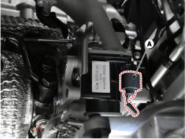
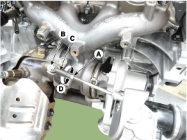
Disconnect the EWGA connector (A).
|
| 4. |
Remove the exhaust manifold heat protector.
(Refer to Engine Mechanical System - "Exhaust Manifold") |
| 5. |
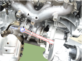
Remove the shaft link assembly (B) after removing the C-ring (A).
|
| 6. |
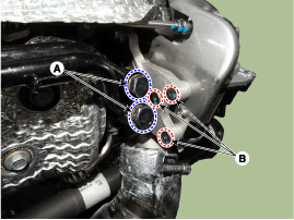
Remove the turbo charger water pipe installation bolt (A). |
| 7. |
Remove the EWGA after removing the bolts (B).
|

| Installation |
| 1. |
Install in the reverse order of removal.
|
| Adjustment |
| 1. |
Check that the waste gate turbo charger is cool enough to work. |
| 2. |
Turn the ignition switch to OFF position. |
| 3. |
Connect the diagnostic tool to DLC connector (16 pin) under the driver side instrument panel. |
| 4. |
Turn the ignition switch ON position.
|
| 5. |
Select VIN or Vehicle on the initial screen. |
| 6. |
Enter "Engine Control" menu after slelecting vehicle
information (Vehicle model, Model year, Engine type) or entering the VIN
number. |
| 7. |
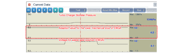
Check " Adaption value for the lower mechancal stop of EWGA" after selecting "Current Data" menu.
|
| 8. |
If the voltage value measured is not within the specified
voltage value, adjust the EWGA rod length. But, if no, no further
procedure is required.
|
| 9. |
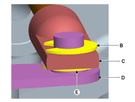
Install the rod end part (C) to the turbo charger lever (D) temporarily. Don't tighten the rod end lock nut (A). |
| 10. |
Turn the ignition switch ON/OFF 5 times. But hold 5 seconds at each IG ON or OFF state.
|

| 11. |
If the voltage value measured is not within the specified
voltage value, repeat 8~10 procedures untill the voltage value is within
the specified voltage value.
|
| 12. |
Check that " Adaption value for the lower mechancal stop of EWGA" is within the specified voltage value. |
| 13. |
If it is within the specified voltage value, install the turbo charger lever (D) and the rod end part (C).
|
| 14. |
Tighten the rod end locking nut (A). The turbo charger lever
(D) side and the rod end part (C) side should be parallel at this time. |
| 15. |
Install the C-ring (B).
|

 RCV Control Solenoid Valve Description and Operation
Description RCV (Recirculation Valve) Control Solenoid Valve is installed on the cooling pan motor top and operates the RCV actuator which controls the by-pass passage of the turbo-charger compressor...
Other information:
Hyundai Sonata LF 2014-2019 Service Manual: Troubleshooting
Trouble Symptom Charts Trouble Symptom 1 Trouble Symptom 2 Trouble symptomProbable causeRemedyThe set vehicle speed varies greatly upward or downward"Surging" (repeated alternating acceleration and deceleration) occurs after settingMalfunction of the vehicle speed sensor circuitRepair the vehicle speed sensor system, or replace the partMalfunction of ECMCheck input and output signals at ECM Trouble Symptom 3 Trouble symptomProbable causeRemedyThe CC system is not canceled when the brake pedal is depressedDamaged or disconnected wiring of the brake pedal switchRepair the harness or replace the brake pedal switchMalfunction of the ECM signalsCheck input and output signals at ECM Trouble Symptom 4 Trouble symptomProbable causeRemedyThe CC system is not canceled when the shift lever is moved to the "N" position (It is canceled, however, when the brake pedal is depressed)Damaged or disconnected wiring of inhibitor switch input circuitRepair the harness or repair or replace the inhibitor switchImproper adjustment of inhibitor switchMalfunction of the ECM signalsCheck input and output signals at ECM Trouble Symptom 5 Trouble symptomProbable causeRemedyCannot decelerate (coast) by using the "SET/–" switchTemporary damaged or disconnected wiring of "SET/–" switch input circuitRepair the harness or replace the "SET/–" switchMalfunction of the ECM signalsCheck input and output signals at ECM Trouble Symptom 6 Trouble symptomProbable causeRemedyCannot accelerate or resume speed by using the "RES/+" switchDamaged or disconnected wiring, or short circuit, or "RES/+" switch input circuitRepair the harness or replace the "RES/+" switchMalfunction of the ECM signalsCheck input and output signals at ECM Trouble Symptom 7 Trouble symptomProbable causeRemedyCC system can be set while driving at a vehicle speed of less than 40km/h (25mph), or there is no automatic cancellation at that speedMalfunction of the vehicle-speed sensor circuitRepair the vehicle speed sensor system, or replace the partMalfunction of the ECM signalsCheck input and output signals at ECM Trouble Symptom 8 Trouble symptomProbable causeRemedyThe cruise main switch indicator lamp does not illuminate (But CC system is normal)Damaged or disconnected bulb of cruise main switch indicator lampRepair the harness or replace the part...
Hyundai Sonata LF 2014-2019 Service Manual: Advanced Smart Cruise Control (ASCC) ECU Schematic Diagrams
C..
Categories
- Manuals Home
- Hyundai Sonata Owners Manual
- Hyundai Sonata Service Manual
- Cooling System
- Engine Control / Fuel System
- General Information
- New on site
- Most important about car
