Hyundai Sonata LF: Engine Control System / Accelerator Position Sensor (APS) Schematic Diagrams
Hyundai Sonata LF 2014-2019 Service Manual / Engine Control / Fuel System / Engine Control System / Accelerator Position Sensor (APS) Schematic Diagrams
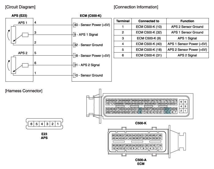
| Circuit Diagram |

 Accelerator Position Sensor (APS) Repair procedures
Inspection 1. Connect the GDS on the Data Link Connector (DLC). 2. Turn the ignition switch ON. 3. Measure the output voltage of the APS 1 and 2 at C...
Other information:
Hyundai Sonata LF 2014-2019 Service Manual: Starter Specifications
S..
Hyundai Sonata LF 2014-2019 Service Manual: Rear Pillar Trim Repair procedures
Replacement • Put on gloves to protect your hands. • When prying with a flat-tip screwdriver or use a prying trim tool, wrap it with protective tape, and apply protective tape around the related parts, to prevent damage...
Categories
- Manuals Home
- Hyundai Sonata Owners Manual
- Hyundai Sonata Service Manual
- Body Electrical System
- Engine Electrical System
- Heating, Ventilation and Air Conditioning
- New on site
- Most important about car

Copyright © 2026 www.hsonatalf.org