Hyundai Sonata LF: Front Suspension System / Front Stabilizer Bar Repair procedures
| 1. |
Raise the vehicle, and make sure it is securely supported. |
| 2. |
Remove the wheel cap (A). 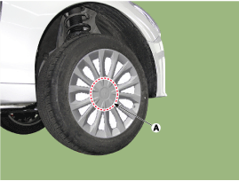
|
Be careful not to damage to the wheel cap (A) when removing the it. |
|
| 3. |
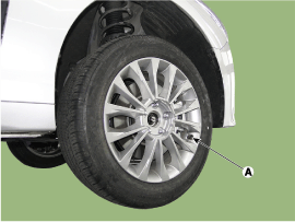
Remove the front wheel and tire (A) from front hub.
Tightening torque :
88.3 ~ 107.9N.m (9.0 ~ 11.0 kgf.m, 65.1 ~ 79.6 lb-ft)
|
|
Be careful not to damage to the hub bolts when removing the front wheel and tire (A). |
|
| 4. |
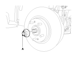
Remove driveshaft nut (A) from the front hub under applying the brake.
Tightening torque :
274.6 ~ 294.2 N.m (28.0 ~ 30.0 kgf.m, 202.5 ~ 217.1 lb-ft)
|
| • |
The front hub coking nut should be replaced with new ones. |
| • |
After installation coking nut (A), stake the coking nut using a chisel and hammer as shown in the illustration below. 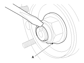
|
|
|
| 5. |
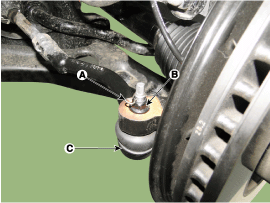
Remove the tie rod end ball joint (C) from the knuckle.
| (1) |
Remove the split pin (A). |
| (2) |
Remove the castle nut (B).
Tightening torque :
34.3 ~ 44.1 N.m (3.5 ~ 4.5 kgf.m, 25.3 ~ 32.5 lb-ft)
|
|
|
| 6. |
Remove the lower arm (A).
| (1) |
Remove the split pin (B). |
| (2) |
Loosen the mounting nut and bolt. 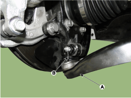
|
|
| 7. |
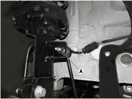
Loosen the stabilizer link (A) and remove it from the shock absorber.
Tightening torque :
98.1 ~ 117.7 N.m (10.0 ~ 12.0 kgf.m, 72.3 ~ 86.8 lb-ft)
|
|
| 8. |
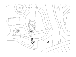
Loosen the universal joint bolt(A) and then disconnect the universal joint assembly.
Tightening torque :
32.4 ~ 37.3 N.m (3.3 ~ 3.8 kgf.m, 23.9 ~ 27.5 lb-ft)
|
|
| 9. |
Remove the engine room under cover (A).
Tightening torque :
7.8 ~ 11.8 N.m (0.8 ~ 1.2 kgf.m, 5.8 ~ 8.7 lb-ft)
|
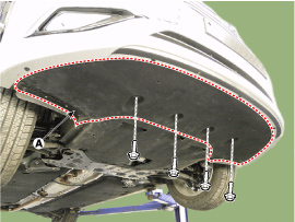
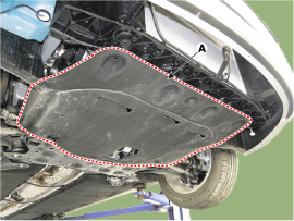
|
| 10. |
Remove the roll rod bracket (A).
Tightening torque :
49.0 ~ 63.7 N.m (5.0 ~ 6.5 kgf.m, 36.2 ~ 47.0 lb-ft)
|
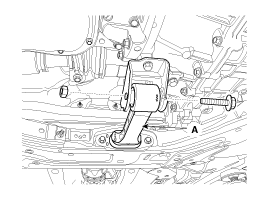
|
| 11. |
Disconnect the muffler rubber hanger (A). 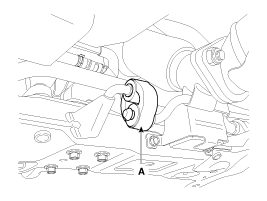
|
| 12. |
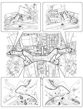
Loosen the bolts & nuts and then remove the sub frame (A).
Tightening torque :
Sub frame mounting bolt & nut
156.9 ~ 176.5N.m(16.0 ~ 18.0kgf.m, 115.7 ~ 130.2lb-ft)
Sub frame stay mounting bolt
44.1 ~ 58.8 N.m(4.5 ~ 6.0kgf.m, 32.5~43.4 lb-ft)
|
|
| 13. |
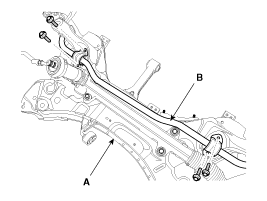
Loosen the mounting bolt and then remove the stabilizer bar (B) from the sub frame (A).
Tightening torque :
49.0 ~ 63.7 N .m (5.0 ~ 6.5 kgf.m, 36.2 ~ 47.0 lb-ft)
|
|
| 14. |
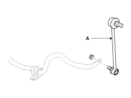
Loosen the nut and then remove the stabilizer link (A) from the stabilizer bar.
Tightening torque :
98.1 ~ 117.7 N.m (10.0 ~ 12.0 kgf.m, 72.3 ~ 86.8 lb-ft)
|
|
| 15. |
Installation is the reverse of removal.
|
| 1. |
Check the bushing for wear and deterioration. |
| 2. |
Check the front stabilizer bar for deformation. |
| 3. |
Check the front stabilizer link ball joint for damage |
Replacement
1.
Raise the vehicle, and make sure it is securely supported.
2.
Remove the wheel cap (A).
Be careful not to damage to the wheel cap (A) when removing the it...
Replacement
1.
Raise the vehicle, and make sure it is securely supported.
2.
Remove the wheel cap (A).
Be careful not to damage to the wheel cap (A) when removing the it...
Other information:
Removal
1.
Turn ignition OFF and disconnect the negative (-) battery cable.
2.
Remove the floor console assembly.
(Refer to Body - “Floor console assembly")
3.
Remove the EPB switch after loosening the screws.
4.
Install in the reverse order of removal...
Description
•
Function
The Transmission Control Module (TCM) is like the brain for
the Dual Clutch Transmission (DCT). It receives information from various
sensors for a wide range of transmission controls to provide an optimal
driving environment for the driver...


 Front Lower Arm Repair procedures
 Sub Frame Repair procedures