Hyundai Sonata LF: Driveshaft Assembly / Front Driveshaft Repair procedures
Hyundai Sonata LF 2014-2019 Service Manual / Driveshaft and axle / Driveshaft Assembly / Front Driveshaft Repair procedures
| Removal |
| 1. |
Raise the vehicle, and make sure it is securely supported. |
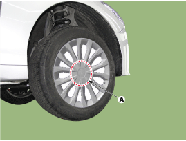
| 2. |
Remove the wheel cap (A).
|

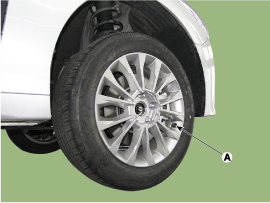
| 3. |
Remove the front wheel and tire (A) from front hub.
|
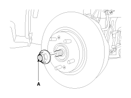
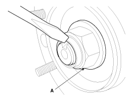
| 4. |
Remove driveshaft nut (A) from the front hub under applying the brake.
|
| 5. |
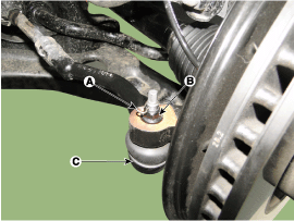
Remove the tie rod end ball joint (C) from the knuckle.
|
| 6. |
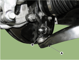
Loosen the lower arm mounting and then remove the lower arm (A).
|
| 7. |
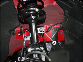
Loosen the stabilizer link (A) and remove it from the shock absorber.
|
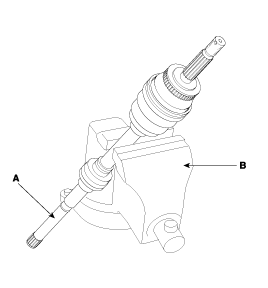
| 8. |
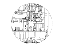
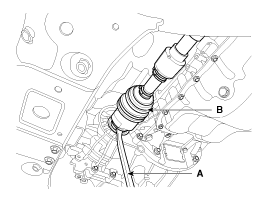
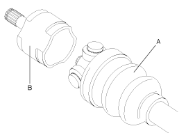
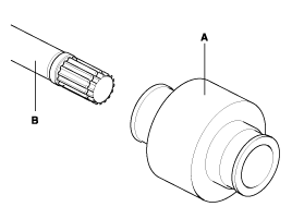
Disconnect the driveshaft (A) from the front hub assembly..
|
| 9. |
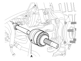
Loosen the inner shaft bearing mounting bolts(A). [T-GDI ONLY]
|
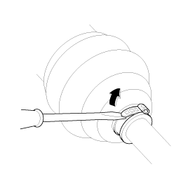
| 10. |
Insert a pry bar (A) between the transaxle case and joint case, and separate the drive shaft (B) from the transaxle case.
|
| 11. |
Install in the reverse order of removal.
|
| Inspection |
| 1. |
Check the driveshaft boots for damage and deterioration. |
| 2. |
Check the driveshaft spline for wear or damage. |
| 3. |
Check that there is no water or foreign material in the joint. |
| 4. |
Check the spider assembly for roller rotation, wear or corrosion. |
| 5. |
Check the groove inside the joint case for wear or corrosion. |
| 6. |
Check the dynamic damper for damage or cracks. |
| Disassembly |
|
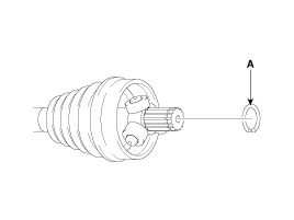
| 1. |
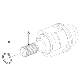
Remove the circlip (B) from the driveshaft spline (A).
|
| 2. |
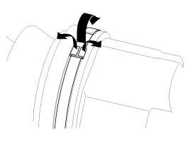
Remove both boot bands from the transaxle side joint(TJ) case.
|
| 3. |
Pull out the boot from transaxle side joint case (B). |
| 4. |
While dividing joint(TJ) boot (A) of the transaxle side, wipe the grease in TJ case (B) and collect them respectively.
|
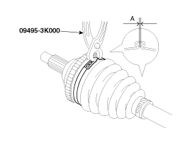
| 5. |
Remove the snap ring (A) from the shaft.
|
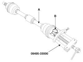
| 6. |
Remove the spider assembly (B) from the driveshaft (A) using the special tool (09495-33000).
|
| 7. |
Clean the spider assembly. |
| 8. |
Remove the boot (A) of the transaxle side joint(TJ).
|
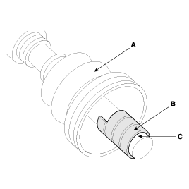
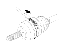
| 9. |
Using a plier or flat-tipped (-) screwdriver, remove the both side of clamp (B) of the dynamic damper (A).
|
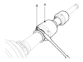
| 10. |
Fix the driveshaft (A) with a vice (B) as illustrated.
|
| 11. |
Apply soap powder on the shaft to prevent being damaged
between the shaft spline and the dynamic damper when the dynamic damper
is removed. |
| 12. |
Saperate the dynamic damper (A) from the shaft (B) carefully.
|
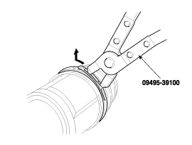
| 13. |
Using a plier or flat-tipped (-) screwdriver, remove the BJ boot band on the side of wheel.
|
| 14. |
Pull out the joint (BJ) on the side of wheel into transaxle direction.
|

| Reassembly |
| 1. |
Wrap tape around the driveshaft spline(TJ) to prevent damage to the boots. |
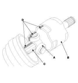
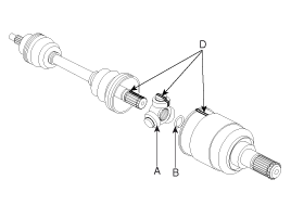
| 2. |
Using the alignment marks (D) made during disassembly as a
guide, install the spider assembly (A) and retainer ring (B) on the
driveshaft splines (C).
|
| 3. |
Add specified grease to the joint boot as much as it was wiped away at inspection. |
| 4. |
Install the both boot band. |
| 5. |
To control the air in the TJ boot, keep the specified distance between the boot bands when they are tightened.
| ||||||||||||||
| 6. |
Using the SST, secure the TJ boot bands.
|
 Front Driveshaft Components and Components Location
Components [THETA 2.4 GDI] 1. Driveshaft (LH)2. Driveshaft (RH)3. Heat protect [THETA 2.0 T-GDI / GAMMA1.6 T-GDI] 1. Driveshaft (LH)2. Driveshaft (RH)3...
 Rear Axle Assembly
Rear Hub - Carrier Components and Components Location Components [EPB Type] 1. Rear carrier assembly2. Dust cover3. Rear hub assembly4. Rear disc brake [General Type] 1...
Categories
- Manuals Home
- Hyundai Sonata Owners Manual
- Hyundai Sonata Service Manual
- Front Driveshaft Repair procedures
- Engine Mechanical System
- Heating, Ventilation and Air Conditioning
- New on site
- Most important about car

Copyright © 2026 www.hsonatalf.org