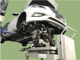
Hyundai Sonata LF: Engine And Transmission Assembly / Engine And Transmission Assembly Repair procedures
Hyundai Sonata LF 2014-2019 Service Manual / Engine Mechanical System / Engine And Transmission Assembly / Engine And Transmission Assembly Repair procedures
| Removal |
| 1. |
Remove the engine cover. |
| 2. |
Remove the battery and battery tray.
(Refer to Engine Electrical System - "Battery") |
| 3. |
Remove the air duct and air cleaner assembly.
(Refer to Intake and Exhaust System - "Air Cleaner") |
| 4. |
Remove the engine room under cover.
(Refer to Engine And Transaxle Assembly - "Engine Room Under Cover") |
| 5. |
Drain the engine coolant.
(Refer to Cooling System - "Coolant") |
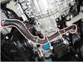
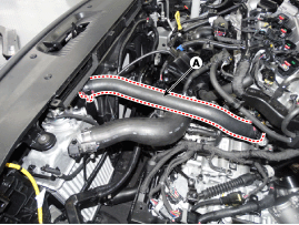
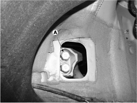
| 6. |
Remove the intercooler inlet hoses & pipe (A).
|
| 7. |
Disconnect the radiator upper hose (A).
|
| 8. |
Disconnect the radiator lower hose (A).
|
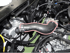
| 9. |
Remove the intercooler outlet hose (A).
|
| 10. |
Recover the refrigerant and then remove the high pressure pipe and low pressure pipe.
(Refer to Heating, Ventilation Air conditioning - "Compressor") |
| 11. |
Remove the transaxle wire harness connectors and control cable from the transaxle.
(Refer to Automatic Transaxle System - "Automatic Transaxle") |
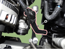
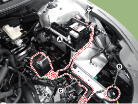
| 12. |
Disconnect the brake booster vacuum hose (A).
|
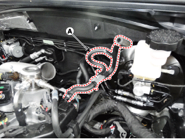
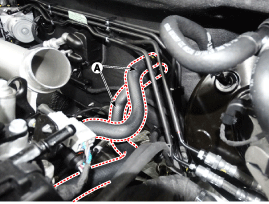
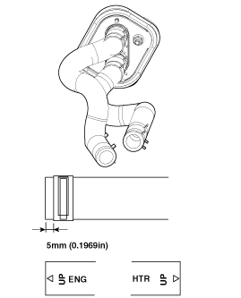
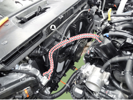
| 13. |
Disconnect the heater hoses (A).
|

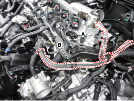
| 14. |
Disconnect the fuel hose (A) and the purge control solenoid valve (PCSV) hose (B).
|
| 15. |
Disconnect the ECM connectors (A) from the ECM, the fuse box
connector (B) from the fuse/relay box and the engine ground line (C).
Then remove the wiring protector (D).
|
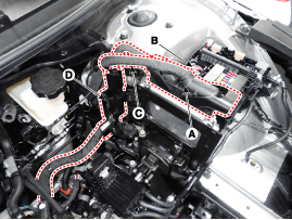
| 16. |
Disconnect the vacuum hose(A).
|
| 17. |
Disconnect the (+) cable (A) from the fuse/relay box and the front connector (B). Then remove the wiring protector (C).
|
| 18. |
Remove the front muffler.
(Refer to Intake And Exhaust System - "Muffler") |
| 19. |
Remove the steering u-joint mounting bolt.
(Refer to Steering System - "Electric Power Steering") |
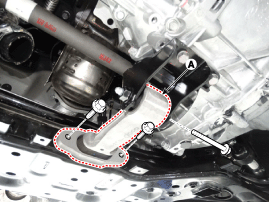
| 20. |
Remove the roll rod bracket (A).
|
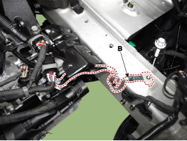
| 21. |
Remove the roll rod mounting support bracket (A).
|
| 22. |
Remove the sub frame.
(Refer to Suspension system - "Sub frame") |
| 23. |
Support the engine and transaxle assembly with a floor jack. |
| 24. |
Disconnect the ground cable (A) and then remove the engine mounting support bracket (B).
|
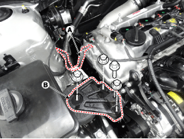
| 25. |
Disconnect the ground line (A).
|
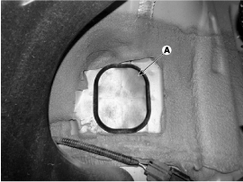
| 26. |
Remove the service cover (A).
|
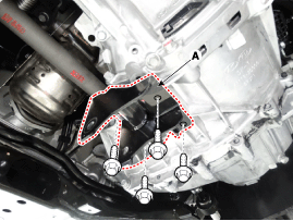
| 27. |
Remove the transaxle mounting bolts (A).
|
| 28. |
Remove the engine and transaxle assembly by lifting vehicle.
|
| Installation |
Installation is in the reverse order of removal.
Perform the following :
| • |
Adjust a shift cable. |
| • |
Adjust the throttle cable. |
| • |
Refill engine with engine oil. |
| • |
Refill a transaxle with fluid. |
| • |
Refill power steering fluid. |
| • |
Refill a radiator and a reservoir tank with engine coolant. |
| • |
Place a heater control knob on "HOT" position. |
| • |
Clean battery posts and cable terminals and assemble. |
| • |
Inspect for fuel leakage. |
| - |
After assemble the fuel line, turn on the ignition switch (do
not operate the starter) so that the fuel pump runs for approximately
two seconds and fuel line pressurizes. |
| - |
Repeat this operation two or three times, then check for fuel leakage at any point in the fuel line. |
| • |
Bleed air from the cooling system. |
| - |
Start engine and let it run until it warms up. (until the radiator fan operates 3 or 4 times.) |
| - |
Turn Off the engine. Check the level in the radiator, add
coolant if needed. This will allow trapped air to be removed from the
cooling system. |
 Engine Mounting Repair procedures
Removal and Installation Rollroad Mounting 1. Rollroad bracket mounting bolts and rollroad bracket (A). Tightening torque Bolt (B) : 107.9 ~ 127...

Other information:
Hyundai Sonata LF 2014-2019 Service Manual: Electro Chromic Inside Rear View Mirror
Components and Components Location Components (1) Components (2) Components (3) Description and Operation Description The ECM (Electro Chromatic inside rear view Mirror) is intended dim the reflecting light in the rear view mirror. The forward facing sensor detects brightness of the surroundings, while the rearward looking sensor is for the light from the rear...
Hyundai Sonata LF 2014-2019 Service Manual: Specifications
S..
Categories
- Manuals Home
- Hyundai Sonata Owners Manual
- Hyundai Sonata Service Manual
- DCT (Dual Clutch Transmission) System
- Cooling System
- Alternator Repair procedures
- New on site
- Most important about car

Copyright © 2026 www.hsonatalf.org