Hyundai Sonata: Cylinder Block / Cylinder Block Repair procedures
Hyundai Sonata LF 2014-2019 Service Manual / Engine Mechanical System / Cylinder Block / Cylinder Block Repair procedures
| Removal |
Engine removal is required for this procedure.
(Refer to Engine and transaxle assembly removal in this group)
| 1. |
MT : Remove the flywheel.
(Refet to Cylinder Block - "Flywheel") |
| 2. |
AT : Remove the drive plate.
(Refet to Cylinder Block - "Drive Plate") |
| 3. |
Remove the engine to engine stand for disassembly. |
| 4. |
Remove the timing chain.
(Refet to Timing System - "Timing Chain") |
| 5. |
Remove the cylinder head.
(Refet to Cylindet Head Assembly - "Cylinder Head") |
| 6. |
Remove the water jacket.
(Refer to Cylinder Block - "Water Jacket") |
| 7. |
Remove the oil level gauge tube. |
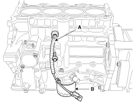
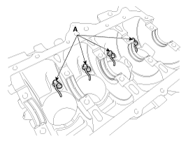
| 8. |
Remove the knock sensor (A) and the oil filter (B).
|
| 9. |
Remove the oil pressure switch.
(Refet to Lubrication System - "Oil Pressure Switch") |
| 10. |
Remove the oil pan.
(Refer to Lubrication System - "Oil Pan") |
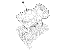
| 11. |
Remove the oil screen (A).
|
| 12. |
Remove the rear oil seal.
(Refet to Cylinder Block - "Rear Oil Seal") |
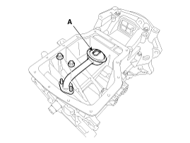
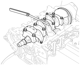
| 13. |
Remove the ladder frame (A).
|
| 14. |
Check the connecting rod end play. |
| 15. |
Remove the connecting rod caps and check oil clearance. |
| 16. |
Remove the piston and connecting rod assemblies.
|

| 17. |
Remove the crankshaft bearing cap and check oil clearance. |
| 18. |
Check the crankshaft end play. |
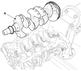
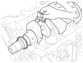
| 19. |
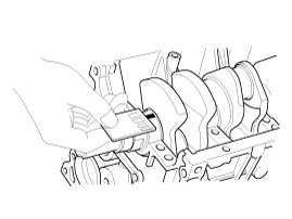
Lift the crankshaft (A) out of the engine, being careful not to damage journals.
|
| 20. |
Remove the piston cooling jet (A).
|
| 21. |
Check fit between piston and piston pin.
Try to move the piston back and forth on the piston pin.
If any movement is felt, replace the piston and pin as a set. |
| 22. |
Remove the piston rings.
|
| 23. |
Remove the connecting rod from the piston.
Using a press, remove the piston pin from piston.
(Press-in load : 500~1,500kg(1,102~3,306lb)) |
| Inspection |
| Connecting Rod And Crankshaft |
| 1. |
Check the connecting rod end play.
Using feeler gauge, measure the end play while moving the connecting rod back and forth.
|
| 2. |
Check the connecting rod bearing oil clearance.
| |||||||||||||||||||||||||||||||||||||||||||||

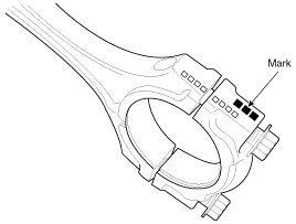
| 3. |
Check the connecting rods.
|
| 4. |
Check the crankshaft bearing oil clearance.
| |||||||||||||||||||||||||||||||||||||||
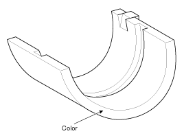
| 5. |
Check the crankshaft end play.
Using a dial indicator, measure the thrust clearance while prying the crankshaft back and forth with a screwdriver.
If the end play is greater than maximum, replace the center bearing. |
Cylinder Block
| 1. |
Remove the gasket material.
Using a gasket scraper, remove all the gasket material from the top surface of the cylinder block. |
| 2. |
Clean the cylinder block
Using a soft brush and solvent, thoroughly clean the cylinder block. |
| 3. |
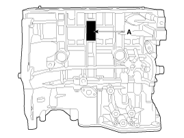
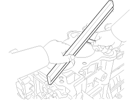
Inspect the top surface of cylinder block for flatness.
Using a precision straight edge and feeler gauge, measure the surface contacting the cylinder head gasket for warpage.
|
| 4. |
Inspect the cylinder bore.
Visually check the cylinder for vertical scratchs.
If deep scratchs are present, replace the cylinder block. |
| 5. |
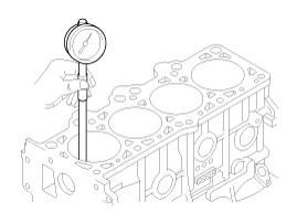
Inspect the cylinder bore diameter.
Using a cylinder bore gauge, measure the cylinder bore diameter at position in the thrust and axial direction.
|
| 6. |
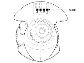
Check the cylinder bore size code on the cylinder block side surface.
Discrimination Of Cylinder Bore Size
|
| 7. |
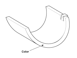
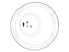
Check the piston size mark (A) on the piston top face.
A : Grade
T : Gasoline engine (T-GDI)
6 : 1.6L
Discrimination Of Piston Outer Diameter
|
| 8. |
Select the piston related to cylinder bore class.
|
Piston And Piston Rings
| 1. |
Clean the piston.
|
| 2. |
The standard measurement of the piston outside diameter is taken 12mm(0.4724in) from bottom land of the piston.
Components
1. Cylinder block2. Ladder frame3. Crank shaft4. Crank shaft upper bearing5. Crank shaft lower bearing6. Thrust bearing7. Main bearing cap8.&n ...
|


