Hyundai Sonata LF: Tire Pressure Monitoring System / TPMS Receiver Schematic Diagrams
Hyundai Sonata LF 2014-2019 Service Manual / Suspension System / Tire Pressure Monitoring System / TPMS Receiver Schematic Diagrams
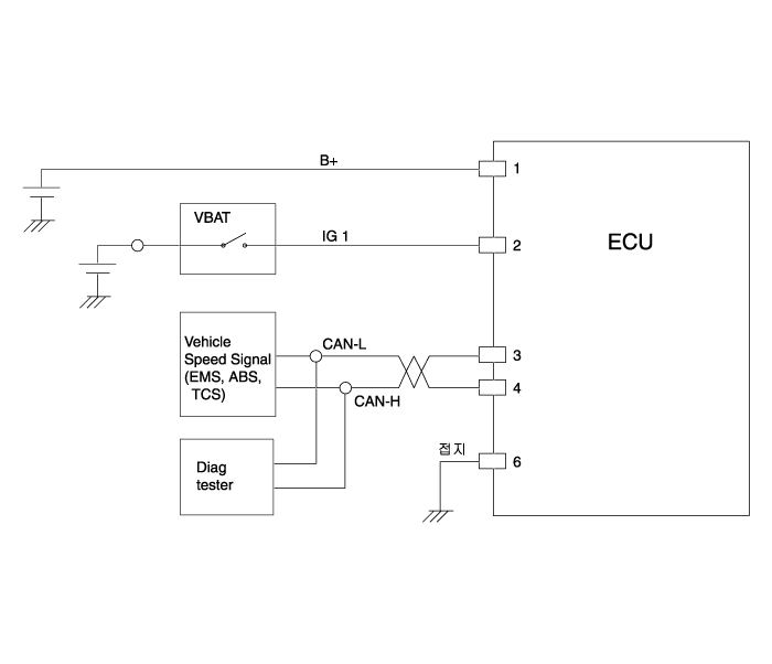
| Circuit Diagram |

| Terminal function |

| Pin NO. | Discription |
| 1 | Battery (+) |
| 2 | IGN |
| 3 | CAN_Low |
| 4 | CAN_High |
| 5 | - |
| 6 | Ground |
 TPMS Receiver Description and Operation
Description 1. Mode (1) Virgin State A. The receiver as a sole part is shipped in this state. Replacement parts should therefore arrive in this state...
 TPMS Receiver Repair procedures
Replacement 1. Disconnect the negative (-) battery cable. 2. Remove the glove box. (Refer to Body - "Crash Pad") 3. Remove faulty part and fit bracket assembly to new part...
Categories
- Manuals Home
- Hyundai Sonata Owners Manual
- Hyundai Sonata Service Manual
- Engine Mechanical System
- Heating, Ventilation and Air Conditioning
- Engine And Transmission Assembly
- New on site
- Most important about car
Copyright В© 2026 www.hsonatalf.org
