Hyundai Sonata LF: General Information / Special Service Tools

Hyundai Sonata LF 2014-2019 Service Manual / Engine Mechanical System / General Information / Special Service Tools

Special Service Tools
Tool (Number and name)
Illustration
Use
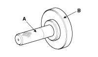
Crankshaft front oil seal installer
(09455-21200)

Installation of the front oil seal
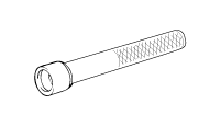
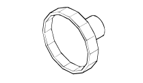
Valve stem oil seal installer
(09222-2B100)

Installation of the valve stem oil seal
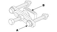
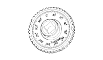
Valve spring compressor and holder
A : (09222-3K000)
B : (09222-3K100)

Removal and installation of the intake or exhaust valve
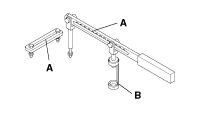
Crankshaft rear oil seal installer
A : (09231-H1100)
B : (09231-2B200)

Installation of the crankshaft rear oil seal
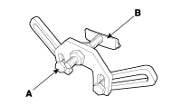
Ring gear stoppper
(09231-2B100) (A)
(09231-3N100) (B)

Removal and installation of crankshaft pulley bolt.
Ring gear stopper
(09231-3D100) (A)
(09231-2W100) (B)

Removal and installation of crankshaft pulley bolt.
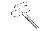
Oil pan remover
(09215-3C000)

Removal of oil pan
Torque angle adapter
(09221-4A000)

Installation of bolts & nuts needing an angular method
Oil filter wrench
(09263-2E000)

Remove and installation of oil filter

    Troubleshooting

    Troubleshooting SymptomSuspect areaRemedyEngine misfire with abnormal internal lower engine noises.Loose or improperly installed engine flywheel.Repair or replace the flywheel as required...

    Engine And Transmission Assembly

    ..

    Other information:

    Hyundai Sonata LF 2014-2019 Service Manual: Troubleshooting


    Trouble Symptom Charts Trouble Symptom 1 Trouble Symptom 2 Trouble symptomProbable causeRemedyThe set vehicle speed varies greatly upward or downward"Surging" (repeated alternating acceleration and deceleration) occurs after settingMalfunction of the vehicle speed sensor circuitRepair the vehicle speed sensor system, or replace the partMalfunction of ECMCheck input and output signals at ECM Trouble Symptom 3 Trouble symptomProbable causeRemedyThe CC system is not canceled when the brake pedal is depressedDamaged or disconnected wiring of the brake pedal switchRepair the harness or replace the brake pedal switchMalfunction of the ECM signalsCheck input and output signals at ECM Trouble Symptom 4 Trouble symptomProbable causeRemedyThe CC system is not canceled when the shift lever is moved to the "N" position (It is canceled, however, when the brake pedal is depressed)Damaged or disconnected wiring of inhibitor switch input circuitRepair the harness or repair or replace the inhibitor switchImproper adjustment of inhibitor switchMalfunction of the ECM signalsCheck input and output signals at ECM Trouble Symptom 5 Trouble symptomProbable causeRemedyCannot decelerate (coast) by using the "SET/–" switchTemporary damaged or disconnected wiring of "SET/–" switch input circuitRepair the harness or replace the "SET/–" switchMalfunction of the ECM signalsCheck input and output signals at ECM Trouble Symptom 6 Trouble symptomProbable causeRemedyCannot accelerate or resume speed by using the "RES/+" switchDamaged or disconnected wiring, or short circuit, or "RES/+" switch input circuitRepair the harness or replace the "RES/+" switchMalfunction of the ECM signalsCheck input and output signals at ECM Trouble Symptom 7 Trouble symptomProbable causeRemedyCC system can be set while driving at a vehicle speed of less than 40km/h (25mph), or there is no automatic cancellation at that speedMalfunction of the vehicle-speed sensor circuitRepair the vehicle speed sensor system, or replace the partMalfunction of the ECM signalsCheck input and output signals at ECM Trouble Symptom 8 Trouble symptomProbable causeRemedyThe cruise main switch indicator lamp does not illuminate (But CC system is normal)Damaged or disconnected bulb of cruise main switch indicator lampRepair the harness or replace the part...

    Hyundai Sonata LF 2014-2019 Service Manual: DCT Control Module (TCM) Schematic Diagrams


    1. TCM Connector and Terminal Function 2. TCM Terminal Function Connector [A] PinDescriptionPinDescription1Clutch Actuator (Clutch Motor 1 (ODD)_Phase V)17-2Clutch actuator (Clutch Motor 2 (EVEN) Phase V)18Clutch Actuator (Clutch Motor 1 (ODD)_HALL 1)3Select Actuator (Shift Solenoid 2 (EVEN)_Ground)19Clutch Actuator (Clutch Motor 1 (ODD)_Supply)4Select Actuator (Shift Solenoid 1 (ODD) Push)20Select Actuator (Shift Solenoid 1 (ODD)_Sensor Supply)5Clutch Actuator (Clutch Motor 1 (ODD)_Phase U)21Select Actuator (Shift Solenoid 2 (EVEN)_Sensor Supply)6Clutch Actuator (Clutch Motor 2 (EVEN)_Phase U)22Select Actuator (Shift Solenoid 2 (EVEN)_Sensor Ouput)7Select Actuator (Shift Solenoid 1 (ODD)_Ground)23Clutch Actuator (Clutch Motor 2 (EVEN)_HALL 2)8Select Actuator (Shift Solenoid 2 (EVEN)_ Pull)24Clutch Actuator (Clutch Motor 2 (EVEN)_HALL 3)9Clutch Actuator (Clutch Motor1 (ODD)_Phase W)25Clutch Actuator (Clutch Motor 2 (EVEN)_Ground)10Clutch Actuator (Clutch Motor 2 (EVEN)_Phase W)26Select Actuator (Shift Solenoid 1 (ODD)_Sensor Output)11Select Actuator (Shift Solenoid 1 (ODD) Pull)27-12Select Actuator (Shift Solenoid 2 (EVEN) Push)28Clutch Actuator (Clutch Motor 2 (EVEN)_HALL 1)13Clutch Actuator (Clutch Motor 1 (ODD)_HALL 2)29Clutch Actuator (Clutch Motor 2 (EVEN)_Supply)14Clutch Actuator (Clutch Motor (ODD)_HALL 3)30Select Actuator (Select Solenoid 1 (ODD)_Sensor Ground)15Clutch Actuator (Clutch Motor 1 (ODD)_Ground)31Select Actuator (Select Solenoid 2 (EVEN)_Sensor Ground)16-32- Connector [B] PinDescriptionPinDescription1-35-2-36-3ON / START Input37-4Paddle Shift (Up) Switch signal38-5Inhibitor Switch "P" Input signal39-6Inhibitor Switch "R" Input signal40-7Inhibitor Switch "D" Input signal41Shift Actuator (Shift Motor 2 (EVEN) _HALL 2)8Sports mode "Down" shift42Shift Actuator (Shift Motor 2 (EVEN) _HALL 3)9Clutch Speed Sensor (EVEN) Ground43Inhibitor Switch "M" Input signal10-44CAN1 Communication Port1 High11-45CAN1 Communication Port1 Low12-46-13Shift Actuator (Shift Motor 1 (ODD) _HALL 2)47-14Shift Actuator (Shift Motor 1 (ODD) _HALL 3)48Flex ray High (BP)15-49Input Speed Supply 1 (ODD)16-50Input Speed Signal 1 (ODD)17Battery Power Low VBD 51-18Paddle Shift Down signal52-19Shift Lever Select Switch53-20Inhibitor Switch "N" Input signal54Shift Actuator (Shift Motor 2 (EVEN) _Supply)21Sports mode "Up" shift55Shift Actuator (Shift Motor 2 (EVEN) _HALL 1)22-56Shift Actuator (Shift Motor 2 (EVEN) _Sensor Ground)23Input Speed Supply 2 (EVEN)57Power Ground 1 for High Current Modules245V spare supply output58Power Ground 2 for High Current Modules25-59Shift Actuator (Shift Motor 2 (EVEN)_Phase W)26Shift Solenoid 1 Position Sensor Output60Shift Actuator (Shift Motor 1 (ODD)_Phase W)27Select Actuator (Shift Motor 1 (ODD)_HALL 1)61 Power Ground 3 for High Current Modules28Select Actuator (Shift Motor 1 (ODD)_Sensor Ground)62-29-63Shift Actuator (Shift Motor 2 (EVEN)_Phase V)30CAN2 Communication Port2 High64Shift Actuator (Shift Motor 1 (ODD)_Phase V)31CAN2 Communication Port2 Low65Motor Supply Voltage 1 from Direct Battery32-66Motor Supply Voltage 2 from Direct Battery33-67Shift Actuator (Shift Motor 2 (EVEN)_Phase U)34Flex ray bus, BM68Shift Actuator (Shift Motor 1 (ODD)_Phase U) 3...

    Categories

    read more

     
    Copyright © 2026 www.hsonatalf.org