Hyundai Sonata LF: Intake And Exhaust System / Intake Manifold Repair procedures
| Removal and Installation |
| 1. |
Remove the engine cover. |
| 2. |
Disconnect the battery negative terminal. |
| 3. |
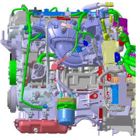
Disconnect the engine wiring connector and haness clamp and disconnect the wiring from intake manifold.
|
| 4. |
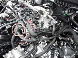
Disconnect the PCV (Positive crankcase ventilation) hose (A) and the PCSV (Purge control solenoid valve) (B).
|
| 5. |
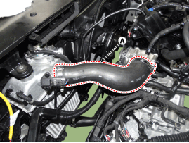
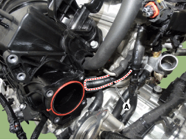
Remove the intercooler outlet hose (A).
|
| 6. |
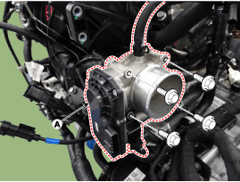
Remove the installation bolts, and then remove the ETC module (A) from the engine.
|
| 7. |
Disconnect the vacuum hose (A).
|
| 8. |
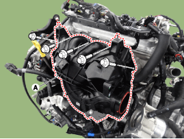
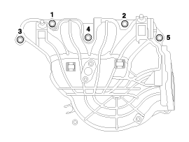
Remove the intake manifold (A) with the gasket.
|
| 9. |
Install in the reverse order of removal. |
 Exhaust Manifold Components and Components Location
Components 1. Turbo manifold gasket2. Turbo manifold module3. Turbo charger coupler4. Turbo charger coupler & gasket5. Oil feed pipe & hose assembly6...
Other information:
Hyundai Sonata LF 2014-2019 Service Manual: Electric WGT Control Actuator Specifications
Specification [EWGA Position Sensor] Position Output Voltage[V] Operating Angle[°] Range of Rod [mm], reference Mechanical Close end stop Position (MCP) 4.8 0 0 Electrical Close end stop Position (ECP) 4.2 12 1.8 Electrical Open end stop Position (EOP) 1 79 16 Mechanical Open end stop Position (MOP) 0...
Hyundai Sonata LF 2014-2019 Service Manual: Parking Brake Assembly Repair procedures
Removal Parking Brake Pedal [Foot type] 1. Remove the crash pad lower panel. (Refer toBody - "Crash Pad") 2. Remove the junction box. (Refer to Body Electrical System - "Fuses and Relays") 3. Disconnect the parking brake switch connector (A)...
Categories
- Manuals Home
- Hyundai Sonata Owners Manual
- Hyundai Sonata Service Manual
- ESP(Electronic Stability Program) System
- Heating, Ventilation and Air Conditioning
- Body Electrical System
- New on site
- Most important about car

