
Hyundai Sonata LF: Body Dimensions / Under Body Body Repair
| Projected Dimensions |
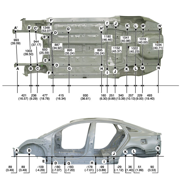
| * These dimensions indicated in this figure are actual-measurement dimensions. [ Unit : mm (inch) ] |
| Actual Measurement Dimensions |
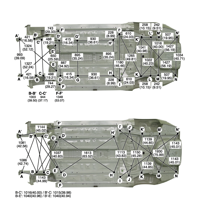
| * These dimensions indicated in this figure are actual-measurement dimensions. [ Unit : mm (inch) ] |
|
|
|
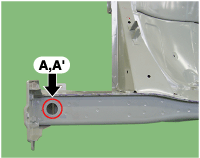
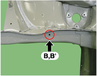
| Front side member tooling hole (O25) | Side cover mounting hole (O9) | Front sub frame mounting bolt |
|
|
|
| Center floor side member tooling hole (O11) | Center floor side member tooling hole (O16) | Floor under cover mounting hole (O6.6) |
|
|
|
| Center floor side member tooling hole (O20) | Center floor side member tooling hole (O20) | Center floor side member tooling hole (O20) |
|
|
|
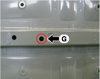
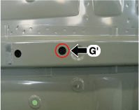
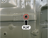
| Rear floor side member tooling hole (O10) | Rear trailing arm mounting hole (O19) | Rear sub frame mounting hole (O22) |
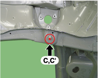
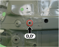
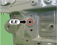
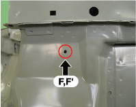
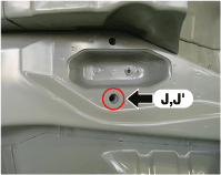
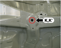
|
|
|
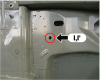
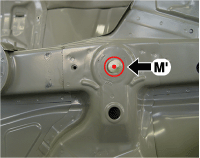
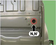
| Rear suspension spring mounting hole (O17) | Rear sub frame mounting pipe | Rear sub frame mounting pipe |
| ||
| Rear floor side member tooling hole (O20) |
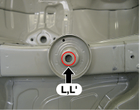
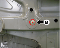
 Rear Body Body Repair
* These dimensions indicated in this figure are actual-measurement dimensions. [ Unit : mm (inch) ] Side outer panel rear cornerSide outer panel rear cornerSide outer panel rear cornerRear combination lamp mounting hole (O6)Rear bumper mounting hole (8...
 Cross Member Body Repair
Front Cross Member * These dimensions indicated in this figure are actual-measurement dimensions. [ Unit : mm (inch) ] Rear Cross Member * These dimensions indicated in this figure are actual-measurement dimensions...
Other information:
Hyundai Sonata LF 2014-2019 Service Manual: Idler Repair procedures
Removal and Installation 1. Remove the drive belt. (Refer to Timing System - "Dreve Belt") 2. Remove the idler (A). Tightening torque : 42.2 ~ 53.9 N.m (4.3 ~ 5.5 kgf.m, 31.1 ~ 39.8 lb-ft) 3. Install in the reverse order of removal...
Hyundai Sonata LF 2014-2019 Service Manual: Alternator Schematic Diagrams
Circuit Diagram • COM signal - When controlling the voltage generated, the ECM sends the target voltage data to the alternator via a PWM signal.(High voltage: 4V or higher, low voltage: 2V or lower) • FR signal - The transistor activation signal inside the alternator monitors the voltage generated by the alternator to control the excitation current before it sends the FR signal to the ECM...
Categories
- Manuals Home
- Hyundai Sonata Owners Manual
- Hyundai Sonata Service Manual
- Emission Control System
- Body Electrical System
- Cylinder Head Cover Repair procedures
- New on site
- Most important about car
