Hyundai Sonata LF: Smart Key System / Smart Key Unit Schematic Diagrams
Hyundai Sonata LF 2014-2019 Service Manual / Body Electrical System / Smart Key System / Smart Key Unit Schematic Diagrams
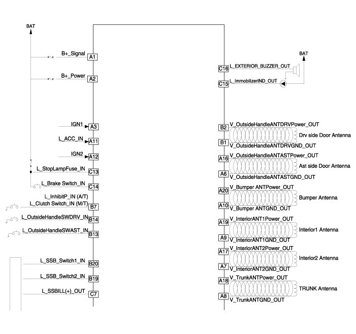
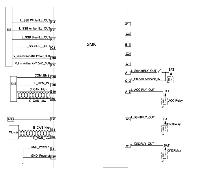
| Circuit Diagram |

 Smart Key Unit Repair procedures
Removal Smart Key Unit 1. Disconnect the negative (-) battery terminal. 2. Remove the glove box. (Refer to Body - "Glove Box Upper Cover Assembly") 3...
Other information:
Hyundai Sonata LF 2014-2019 Service Manual: Rear Disc Brake Components and Components Location
C..
Hyundai Sonata LF 2014-2019 Service Manual: Description and Operation
Description The Evaporative Emission Control System prevents fuel vapor stored in fuel tank from vaporizing into the atmosphere. When the fuel evaporates in the fuel tank, the vapor passes through vent hoses or tubes to a canister filled with charcoal...
Categories
- Manuals Home
- Hyundai Sonata Owners Manual
- Hyundai Sonata Service Manual
- Emission Control System
- Driveshaft and axle
- Heating, Ventilation and Air Conditioning
- New on site
- Most important about car

Copyright © 2026 www.hsonatalf.org