Hyundai Sonata LF: Smart Key System / Smart Key Unit Components and Components Location
Hyundai Sonata LF 2014-2019 Service Manual / Body Electrical System / Smart Key System / Smart Key Unit Components and Components Location
| Components (1) |
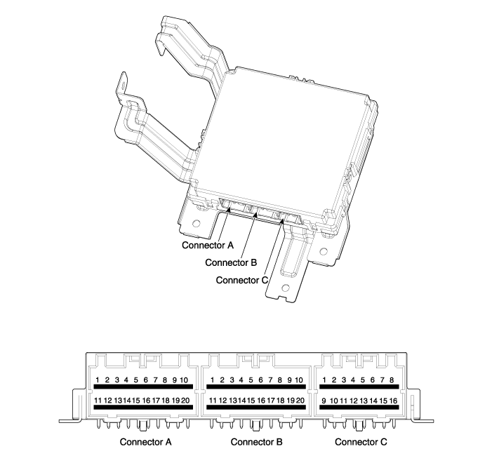
| No | Connector A | Connector B | Connector C |
| 1 | BAT (+)_Signal | Driver's door antenna_GND | - |
| 2 | BAT (+)_Power | Driver's door antenna_Power | - |
| 3 | IGN 1 | - | - |
| 4 | IGN 2_Relay output | B-CAN (High) | SSB LED (OFF) |
| 5 | IGN 1_Relay output | B-CAN (Low) | SSB LED (IGN) |
| 6 | Assist door antenna_GND | Wheel speed sensor | SSB LED (ACC) |
| 7 | Interior antenna 2_GND | AT : 'P' signal input MT : Clutch switch signal input | SSB Illumination (+) |
| 8 | Trunk antenna_GND | - | SSB Illumination (-) |
| 9 | Interior antenna 1_GND | C-CAN (Low) | Immoblizer antenna_GND |
| 10 | Bumpper antenna_GND | C-CAN (High) | Immoblizer antenna_Power |
| 11 | ACC | GND 1 | - |
| 12 | IGN2 | GND 2 | Start signal feedback |
| 13 | ACC_Relay output | Assist door switch_signal | Stop lamp fuse |
| 14 | Starter_Relay output | Driver's door switch_signal | Brake switch |
| 15 | - | - | Immoblizer indicator |
| 16 | Assist door antenna_Power | EMS CAN | Exterior buzzer |
| 17 | Interior antenna 2_Power | - | ? |
| 18 | Trunk antenna_Power | RPM_Input | |
| 19 | Interior antenna 1_Power | SSB switch2 | |
| 20 | Bumpper antenna_Power | SSB switch1 |
 Smart Key Repair procedures
Smart Key Smart Key Code Saving 1. Connect the DLC cable of GDS to the data link connector (16 pins) in driver side crash pad lower panel, turn the power on GDS...

Other information:
Hyundai Sonata LF 2014-2019 Service Manual: ESP Control Unit Repair procedures
Removal 1. Turn the ignition switch OFF. 2. Pull up the lock of the HECU connector , then disconnect the connector. 3. Disconnect the brake tubes from the HECU by unlocking the nuts counterclockwise with a spanner. Tightening torque : ABS : 13...
Hyundai Sonata LF 2014-2019 Service Manual: Cylinder Block Components and Components Location
Components 1. Cylinder block2. Ladder frame3. Crank shaft4. Crank shaft upper bearing5. Crank shaft lower bearing6. Thrust bearing7. Main bearing cap8. Crank shaft sproket9. Crank shaft pulley10...
Categories
- Manuals Home
- Hyundai Sonata Owners Manual
- Hyundai Sonata Service Manual
- Audio
- Brake System
- Body Electrical System
- New on site
- Most important about car

Copyright © 2026 www.hsonatalf.org