
Hyundai Sonata LF: SRSCM / Schematic Diagrams
| Circuit Diagram (1) |
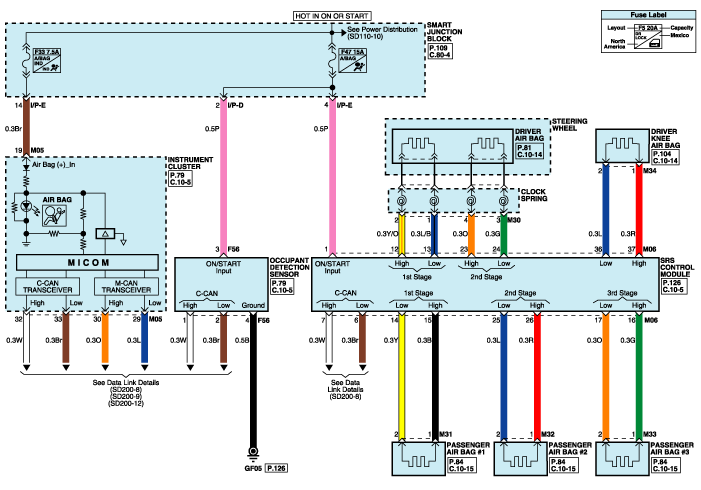
| Circuit Diagram (2) |
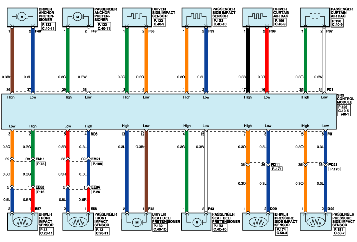
| Circuit Diagram (3) |
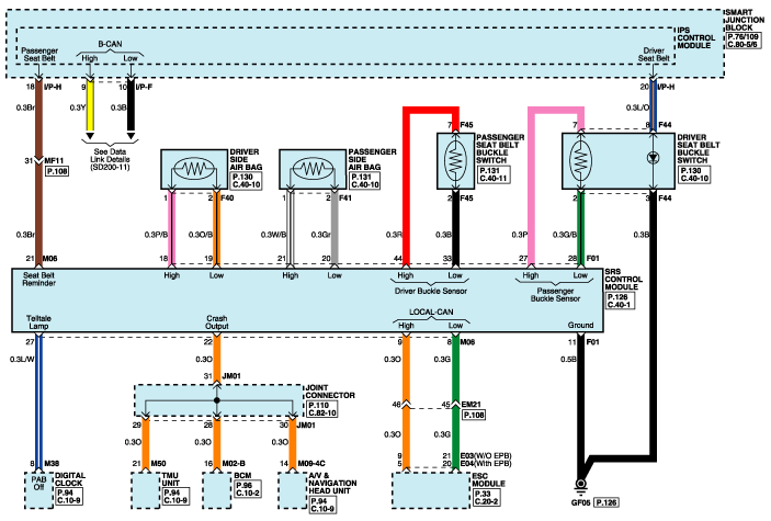
| SRSCM Connector Terminal |
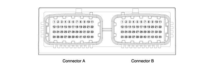
| Pin | Function (Connector A) | Pin | Function (Connector B) |
| A1 | IGN-1 | B1 | Side impact sensor front, Passenger-High (+) |
| A2 | Front impact sensor driver-High (+) | B2 | Side impact sensor front, Passenger-Low (-) |
| A3 | Front impact sensor driver-Low (-) | B3 | Side impact sensor front, Driver-High (+) |
| A4 | Front impact sensor passenger-High (+) | B4 | Side impact sensor front, Driver-Low (-) |
| A5 | Front impact sensor passenger-Low (-) | B5 | Pressure side impact sensor passenger-High (+) |
| A6 | C-CAN ACU to Vehicle-Low (-) | B6 | Pressure side impact sensor passenger-Low (-) |
| A7 | C-CAN ACU to Vehicle-High (+) | B7 | Pressure side impact sensor driver-High (+) |
| A8 | Local CAN IMU to ESC-Low (-) | B8 | Pressure side impact sensor driver-Low (-) |
| A9 | Local CAN IMU to ESC-High (+) | B9 | - |
| A10 | - | B10 | - |
| A11 | - | B11 | Ground |
| A12 | Driver airbag 1st stage-High (+) | B12 | Retractor pretensioner front, Driver-Low (-) |
| A13 | Driver airbag 1st stage-Low (-) | B13 | Retractor pretensioner front, Driver-High (+) |
| A14 | Passenger airbag 1st stage-Low (-) | B14 | Retractor pretensioner front, Passenger-High (+) |
| A15 | Passenger airbag 1st stage-High(+) | B15 | Retractor pretensioner front, Passenger-Low (-) |
| A16 | Passenger airbag active vent-High (+) | B16 | Curtain airbag driver-Low (-) |
| A17 | Passenger airbag active vent-Low (-) | B17 | Curtain airbag driver-High (+) |
| A18 | - | B18 | Side airbag front, driver-High (+) |
| A19 | - | B19 | Side airbag front, driver-Low (-) |
| A20 | - | B20 | Side airbag front, passenger-Low (-) |
| A21 | Seat belt reminder | B21 | Side airbag front, passenger-High (+) |
| A22 | Crash output | B22 | - |
| A23 | Driver airbag 2nd stage-High (+) | B23 | - |
| A24 | Driver airbag 2nd stage-Low (-) | B24 | - |
| A25 | Passenger airbag 2nd stage-Low (-) | B25 | - |
| A26 | Passenger airbag 2nd stage-High (+) | B26 | - |
| A27 | Passenger airbag OFF lamp (telltale lamp) | B27 | Seat belt buckle sensor front, Driver-High (+) |
| A28 | - | B28 | Seat belt buckle sensor front, Driver-Low(-) |
| A29 | - | B29 | - |
| A30 | - | B30 | - |
| A31 | - | B31 | - |
| A32 | - | B32 | - |
| A33 | - | B33 | Seat belt buckle sensor front, Passenger-Low (-) |
| A34 | - | B34 | Curtain airbag passenger-Low (-) |
| A35 | - | B35 | Curtain airbag passenger-High (+) |
| A36 | Knee airbag driver-Low (-) | B36 | Anchor pretensioner driver-High (+) |
| A37 | Knee airbag driver-High (+) | B37 | Anchor pretensioner driver-Low (-) |
| A38 | - | B38 | Anchor pretensioner passenger-Low (-) |
| A39 | - | B39 | Anchor pretensioner passenger-High (+) |
| A40 | - | B40 | - |
| A41 | - | B41 | - |
| A42 | - | B42 | - |
| A43 | - | B43 | - |
| A44 | - | B44 | Seat belt buckle sensor front, Passenger-High (-) |
 Seat Belt Buckle Switch (BS) Repair procedures
Removal 1. Disconnect the battery negative cable, and wait for at least three minutes before beginning work. 2. Remove the front seat assembly...

Other information:
Hyundai Sonata LF 2014-2019 Service Manual: DCT Control Module (TCM) Schematic Diagrams
1. TCM Connector and Terminal Function 2. TCM Terminal Function Connector [A] PinDescriptionPinDescription1Clutch Actuator (Clutch Motor 1 (ODD)_Phase V)17-2Clutch actuator (Clutch Motor 2 (EVEN) Phase V)18Clutch Actuator (Clutch Motor 1 (ODD)_HALL 1)3Select Actuator (Shift Solenoid 2 (EVEN)_Ground)19Clutch Actuator (Clutch Motor 1 (ODD)_Supply)4Select Actuator (Shift Solenoid 1 (ODD) Push)20Select Actuator (Shift Solenoid 1 (ODD)_Sensor Supply)5Clutch Actuator (Clutch Motor 1 (ODD)_Phase U)21Select Actuator (Shift Solenoid 2 (EVEN)_Sensor Supply)6Clutch Actuator (Clutch Motor 2 (EVEN)_Phase U)22Select Actuator (Shift Solenoid 2 (EVEN)_Sensor Ouput)7Select Actuator (Shift Solenoid 1 (ODD)_Ground)23Clutch Actuator (Clutch Motor 2 (EVEN)_HALL 2)8Select Actuator (Shift Solenoid 2 (EVEN)_ Pull)24Clutch Actuator (Clutch Motor 2 (EVEN)_HALL 3)9Clutch Actuator (Clutch Motor1 (ODD)_Phase W)25Clutch Actuator (Clutch Motor 2 (EVEN)_Ground)10Clutch Actuator (Clutch Motor 2 (EVEN)_Phase W)26Select Actuator (Shift Solenoid 1 (ODD)_Sensor Output)11Select Actuator (Shift Solenoid 1 (ODD) Pull)27-12Select Actuator (Shift Solenoid 2 (EVEN) Push)28Clutch Actuator (Clutch Motor 2 (EVEN)_HALL 1)13Clutch Actuator (Clutch Motor 1 (ODD)_HALL 2)29Clutch Actuator (Clutch Motor 2 (EVEN)_Supply)14Clutch Actuator (Clutch Motor (ODD)_HALL 3)30Select Actuator (Select Solenoid 1 (ODD)_Sensor Ground)15Clutch Actuator (Clutch Motor 1 (ODD)_Ground)31Select Actuator (Select Solenoid 2 (EVEN)_Sensor Ground)16-32- Connector [B] PinDescriptionPinDescription1-35-2-36-3ON / START Input37-4Paddle Shift (Up) Switch signal38-5Inhibitor Switch "P" Input signal39-6Inhibitor Switch "R" Input signal40-7Inhibitor Switch "D" Input signal41Shift Actuator (Shift Motor 2 (EVEN) _HALL 2)8Sports mode "Down" shift42Shift Actuator (Shift Motor 2 (EVEN) _HALL 3)9Clutch Speed Sensor (EVEN) Ground43Inhibitor Switch "M" Input signal10-44CAN1 Communication Port1 High11-45CAN1 Communication Port1 Low12-46-13Shift Actuator (Shift Motor 1 (ODD) _HALL 2)47-14Shift Actuator (Shift Motor 1 (ODD) _HALL 3)48Flex ray High (BP)15-49Input Speed Supply 1 (ODD)16-50Input Speed Signal 1 (ODD)17Battery Power Low VBD 51-18Paddle Shift Down signal52-19Shift Lever Select Switch53-20Inhibitor Switch "N" Input signal54Shift Actuator (Shift Motor 2 (EVEN) _Supply)21Sports mode "Up" shift55Shift Actuator (Shift Motor 2 (EVEN) _HALL 1)22-56Shift Actuator (Shift Motor 2 (EVEN) _Sensor Ground)23Input Speed Supply 2 (EVEN)57Power Ground 1 for High Current Modules245V spare supply output58Power Ground 2 for High Current Modules25-59Shift Actuator (Shift Motor 2 (EVEN)_Phase W)26Shift Solenoid 1 Position Sensor Output60Shift Actuator (Shift Motor 1 (ODD)_Phase W)27Select Actuator (Shift Motor 1 (ODD)_HALL 1)61 Power Ground 3 for High Current Modules28Select Actuator (Shift Motor 1 (ODD)_Sensor Ground)62-29-63Shift Actuator (Shift Motor 2 (EVEN)_Phase V)30CAN2 Communication Port2 High64Shift Actuator (Shift Motor 1 (ODD)_Phase V)31CAN2 Communication Port2 Low65Motor Supply Voltage 1 from Direct Battery32-66Motor Supply Voltage 2 from Direct Battery33-67Shift Actuator (Shift Motor 2 (EVEN)_Phase U)34Flex ray bus, BM68Shift Actuator (Shift Motor 1 (ODD)_Phase U) 3...
Hyundai Sonata LF 2014-2019 Service Manual: DCT Control Module (TCM) Repair procedures
Inspection Transmission Control Module (TCM) Inspection Procedure 1. Inspecting TCM ground circuit: Measure the resistance between the TCM and chassis ground. (Check the terminal connected to the chassis ground while using the back of the harness connector as the base point for TCM...
Categories
- Manuals Home
- Hyundai Sonata Owners Manual
- Hyundai Sonata Service Manual
- Engine And Transmission Assembly
- Engine Control / Fuel System
- Engine Electrical System
- New on site
- Most important about car
