Hyundai Sonata LF: Evaporative Emission Control System / Repair procedures
| Inspection |
| 1. |
Disconnect the vapor hose from the intake manifold and connect a vacuum pump to the nipple on the intake manifold.
· At Cold Engine [Engine Coolant Temperature < 60°C(140°F)]
|
| 2. |
Check the following points with applied vacuum at the purge control solenoid valve (PCSV).
· At Warmed Engine [Engine Coolant Temperature > 80°C(176°F)]
|
| 1. |
Turn ignition switch OFF and disconnect the negative (-) battery cable. |
| 2. |
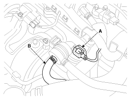
Disconnect the PCSV connector (A). |
| 3. |
Disconnect the vapor hose (B) which is connected to the intake manifold from the PCSV.
|
| 4. |
After connecting a vacuum pump to the nipple, apply vacuum. |
| 5. |
With the PCSV control line grounded, check the valve
operation with battery voltage applied to the PCSV(Open) and
removed(Closed).
|
| 6. |
Measure the coil resistance of the PCSV.
|
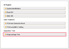
| 1. |
Select "Evap. Leakage Test".
|
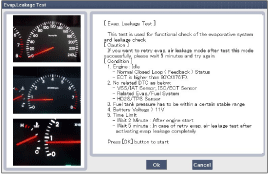
| 2. |
Proceed with the test according to the screen introductions.
|
 Schematic Diagrams
Schematic Diagram Canister The Canister is filled with charcoal and absorbs evaporated fuel vapor from the fuel tank. The gathered fuel vapor in canister is drawn into the intake manifold by the ECM/PCM when appropriate conditions are set...
 Canister Repair procedures
Removal 1. Turn the ignition switch OFF and disconnect the negative (-) battery cable. 2. Remove the fuel tank. (Refer to Engine Control / Fuel System - " Fuel Tank") 3...
Other information:
Hyundai Sonata LF 2014-2019 Service Manual: Coolant Repair procedures
Replacement And Air Bleeding Never remove the radiator cap when the engine is hot. Serious scalding could be caused by hot fluid under high pressure escaping from the radiator. When pouring engine coolant, be sure to shut the relay box lid and not to let coolant spill on the electrical parts or the paint...
Hyundai Sonata LF 2014-2019 Service Manual: Shift Lever Repair procedures
Removal 1. Disconnect a boots from the console upper cover. 2. Pull the knob (A) in the direction of "F" and remove the knob. 3. Remove the floor console assembly. (Refer to Body - "Floor Console") 4. Disconnect the connector (A) from the shift lever...
Categories
- Manuals Home
- Hyundai Sonata Owners Manual
- Hyundai Sonata Service Manual
- Engine Control / Fuel System
- Body Electrical System
- Engine Mechanical System
- New on site
- Most important about car
