Hyundai Sonata LF: General Information / General Safety Information and Caution
| Precautions |
| General Precautions |
| • |
Except when performing electrical inspections, always turn
the ignition switch OFF and disconnect the negative cable from the
battery, and wait at least three minutes before beginning work. |
The contents in the memory are not erased even if the
ignition switch is turned OFF or the battery cables are disconnected
from the battery. |

| • |
Use the replacement parts which are manufactured to the same standards as the original parts and quality.
Do not install used SRS parts from another vehicle. Use only new parts when making SRS repairs. |
| • |
Carefully inspect any SRS part before you install it. Do not
install any part that shows signs of being dropped or improperly
handled, such as dents, cracks or deformation.
|
| • |
Before removing any of the SRSCM parts (including the disconnection of the connectors), always disconnect the SRSCM connector. |
| • |
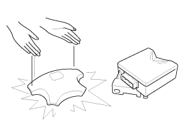
Store the removed airbag with the pad surface up. |
| • |
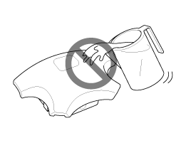
Keep free from any oil, grease, detergent, or water to prevent damage to the airbag assembly.
|
| • |
Store the removed airbag on secure, flat surface away from any high heat source (exceeding 85 C/185 F). |
| • |
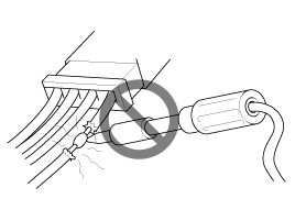
Never perform electrical inspections to the airbags, such as measuring resistance. |
| • |
Do not position yourself in front of the airbag assembly during removal, inspection, or replacement. |
| • |
Refer to the scrapping procedures for disposal of the damaged airbag. |
| • |
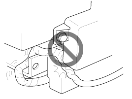
Be careful not to bump or impact the SRS unit or the side
impact sensors or front impact sensors whenever the ignition switch is
ON, wait at least three minutes after the ignition switch is turned OFF
before begin work. |
| • |
During installation or replacement, be careful not to bump
(by impact wrench, hammer, etc.) the area around the SRS unit and the
side impact sensor and the front impact sensors. The airbags could
accidentally deploy and cause damage or injury. |
| • |
Replace the front airbag module, SRSCM, FIS when the front
airbag is deployed. Replace the airbag wiring when the airbag wiring get
damaged. Replace the side airbag module, the curtain airbag module,
SRSCM, SIS when deploying the side airbag. Replace the airbag when the
airbag wiring get damaged. |
| • |
After a collision in which the airbags or the side air bags
did not deploy, inspect for any damage or any deformation on the SRS
unit and the side impact sensors. If there is any damage, replace the
SRS unit, the front impact sensor and/or the side impact sensors. |
| • |
Do not disassemble the SRS unit, the front impact sensor or the side impact sensors. |
| • |
Turn the ignition switch OFF, disconnect the battery negative
cable and wait at least three minutes before beginning installation or
replacement of the SRS unit. |
| • |
Be sure the SRS unit, the front impact sensor and side impact sensors are installed securely with the mounting bolts. |
| • |
Do not spill water or oil on the SRS unit, or the front impact sensor or the side impact sensors and keep them away from dust. |
| • |
Store the SRS unit, the front impact sensor and the side
impact sensors in a cool (15 ~ 25 C/ 59 ~ 77 F) and dry (30 ~ 80%
relative humidity, no moisture) area. |
| • |
Never attempt to modify, splice, or repair SRS wiring. If there is an open or damage in SRS wiring, replace the harness.
|
| • |
Be sure to install the harness wires so that they are not pinched, or interfere with other parts.
|
| • |
Make sure all SRS ground locations are clean, and grounds are
securely fastened for optimum metal-to-metal contact. Poor grounding
can cause intermittent problems that are difficult to diagnose. |
| • |
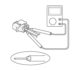
When using electrical test equipment, insert the probe of the tester into the wire side of the connector.
Do not insert the probe of the tester into the terminal side of the connector, and do not tamper with the connector.
|
| • |
Use a u-shaped probe. Do not insert the probe forcibly. |
| • |
Use specified service connectors for troubleshooting.
Using improper tools could cause an error in inspection due to poor metal contact. |
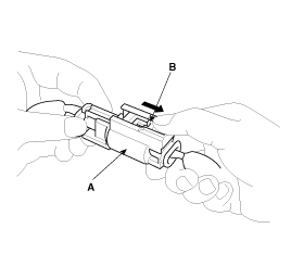
| Disconnecting |
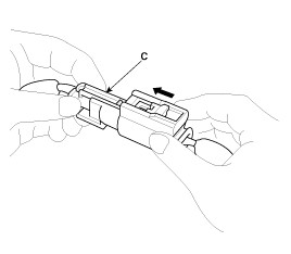
| Connecting |
 Special Service Tools
Special Service Tools Tool(Number and Name)IllustrationUseDeployment tool0957A-34100AAirbag deployment tool.Deployment adapter0957A-3Q100Use with deployment tool...
 Description and Operation
Warning Lamp Activation Warning Lamp Behavior after Ignition On As soon as the operating voltage is applied to the SRSCM ignition input, the SRSCM activates the warning lamp for a LED lamp check...
Other information:
Hyundai Sonata LF 2014-2019 Service Manual: Advanced Smart Cruise Control (ASCC) Switch Repair procedures
Inspection [Measuring Resistance] 1. Disconnect the smart cruise control switch connector from the control switch. 2. Measure resistance between terminals on the control switch when each function switch is ON (switch is depressed). Function switchTerminalResistanceSET -3 - 5550?±5%RES +3 - 5880?±5%CANCEL3 - 5330?±5%CRUISE3 - 51...
Hyundai Sonata LF 2014-2019 Service Manual: Components and Components Location
Components [Manual Seat Type] 1. Front seat headrest2. Front seat headrest guide3. Front seat back board4. Front seat back frame assembly5. Front seat back pad6. Front seat back heater7. Front seat cushion frame assembly8. Front seat shield cushion pad9...
Categories
- Manuals Home
- Hyundai Sonata Owners Manual
- Hyundai Sonata Service Manual
- Suspension System
- Brake System
- DCT (Dual Clutch Transmission) System
- New on site
- Most important about car
