Hyundai Sonata LF: Dual Clutch System / Dual Clutch Assembly Repair procedures
Hyundai Sonata LF 2014-2019 Service Manual / DCT (Dual Clutch Transmission) System / Dual Clutch System / Dual Clutch Assembly Repair procedures
| Removal |
| 1. |
Remove the dual clutch transmission from the vehicle.
(Refer to Dual Clutch System - "Repair procedures") |
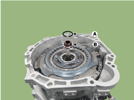
| 2. |
Remove the retaining (A) and then removing the spline hub (B).
|
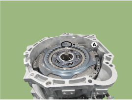
| 3. |
Remove the snap ring (A).
|
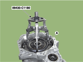
| 4. |
Remove the dual clutch assembly (A) by using the special service tool [SST No.: 09430-C1180].
|
| Installation |
|

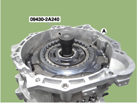
| 1. |
Install the SST (No.:09430-2A240) on the support bearing within the dual clutch assembly (A).
|
| 2. |
Install the SST (No. : 09430-2A240) on the clutch housing side. |
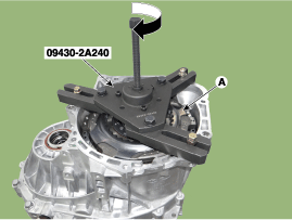
| 3. |
Install the dual clutch assembly (A) using the SST (No. : 09430-2A240).
|
| 4. |
Install the snap ring (A).
|
| 5. |
Install the spline hub (B) and the install the snap ring (A).
|
| 6. |
Perform the work procedures for abrasion compensation reset after installing the new dual clutch assembly.
(Refer to Clutch Actuator Assembly - "Adjustment") |
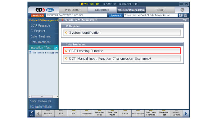
| 7. |
Perform the clutch touch point learning procedure using the GDS after replacing the dual clutch assembly.
|


Other information:
Hyundai Sonata LF 2014-2019 Service Manual: Blower Unit Components and Components Location
Component Location 1. Blower unit assembly Components 1. Intake actuator2. Intake case [LH]3. Intake door assembly4. Air filter5. Filter cover assembly6. Intake inlet seal 7. Intake case [RH]8. Intake outlet seal 9. Blower upper cover10. Blower unit pad11...
Hyundai Sonata LF 2014-2019 Service Manual: Rear Glass Defogger Printed Heater Repair procedures
Inspection Wrap tin foil around the end of the voltmeter test lead to prevent damaging the heater line. Apply finger pressure on the tin foil, moving the tin foil along the grid line to check for open circuits. 1. Turn on the defogger switch and use a voltmeter to measure the voltage of each heater line at the glass center point...
Categories
- Manuals Home
- Hyundai Sonata Owners Manual
- Hyundai Sonata Service Manual
- Timing System
- Engine Control / Fuel System
- Air Conditioning System
- New on site
- Most important about car
Copyright © 2025 www.hsonatalf.org