Hyundai Sonata LF: Engine Control System / Ambient Temperature Sensor (ATS) Repair procedures
Hyundai Sonata LF 2014-2019 Service Manual / Engine Control / Fuel System / Engine Control System / Ambient Temperature Sensor (ATS) Repair procedures
| Inspection |
| 1. |
Turn the ignition switch OFF. |
| 2. |
Disconnect the ATS connector. |
| 3. |
Measure resistance between the ATS terminals 1 and 2 [B1/S1]. |
| 4. |
Check that the resistance is within the specification.
|
| Removal |
| 1. |
Turn the ignition switch OFF and disconnect the battery negative (-) cable. |
| 2. |
Remove the under cover front pannel.
(Refer to Engine Mechanical System - "Engine and Transaxle Assembly") |
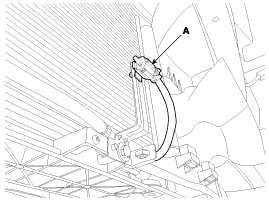
| 3. |
Disconnect the connector, an then remove the ambient temperature sensor (A).
|
| Installation |
|

| 1. |
Install in the reverse order of removal. |

 Boost Pressure Sensor (BPS) Description and Operation
Description The Boost Pressure Sensor (BPS) is installed on the intercooler assembly and measures the pressure of the compressed air in turbocharger...
Other information:
Hyundai Sonata LF 2014-2019 Service Manual: Seat Heater Components and Components Location
C..
Hyundai Sonata LF 2014-2019 Service Manual: Front Seat Frame Assembly Repair procedures
Replacement • Put on gloves to protect your hands. • When prying with a flat-tip screwdriver or use a prying trim tool, wrap it with protective tape, and apply protective tape around the related parts, to prevent damage...
Categories
- Manuals Home
- Hyundai Sonata Owners Manual
- Hyundai Sonata Service Manual
- Engine Control System
- Driveshaft and axle
- Timing System
- New on site
- Most important about car

Copyright © 2026 www.hsonatalf.org