
Hyundai Sonata LF: Controller / Heater & A/C Control Unit (Manual) Components and Components Location
Hyundai Sonata LF 2014-2019 Service Manual / Heating, Ventilation and Air Conditioning / Controller / Heater & A/C Control Unit (Manual) Components and Components Location
| Components |
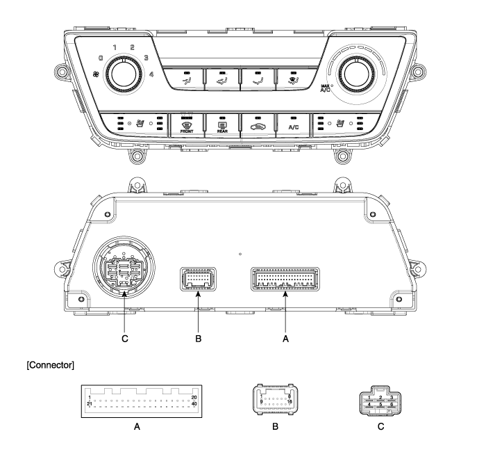
Connector [A]
| Pin NO | Function | Pin NO | Function |
| 1 | ILL+ (TAIL) | 21 | Detent OUT (+) |
| 2 | Sensor REF (+5V) | 22 | HTD |
| 3 | Mode control actuator (Vent) | 23 | Rear defog switch |
| 4 | Mode control actuator (Defrost) | 24 | C_CAN High |
| 5 | Mode control actuator (Feedback) | 25 | C_CAN Low |
| 6 | Intake actuator (Fresh) | 26 | ECV+ |
| 7 | Intake actuator (Recirculation) | 27 | ECV- (Ground) |
| 8 | Intake actuator (Feedback) | 28 | AMB Sensor (+) |
| 9 | Driver's temperature control actuator (Cool) | 29 | EVAP Sensor (+) |
| 10 | Driver's temperature control actuator (Warm) | 30 | Blower MAX signal |
| 11 | Driver's temperature control actuator (Feedback) | 31 | Blower ON signal |
| 12 | Driver's seat heat indicator (Low) | 32 | - |
| 13 | Driver's seat heat indicator (Mid) | 33 | - |
| 14 | Driver's seat heat indicator (High) | 34 | - |
| 15 | Passenger's seat heat indicator (Low) | 35 | - |
| 16 | Driver's seat heat switch | 36 | - |
| 17 | Passenger's seat heat switch | 37 | - |
| 18 | Driver's cool switch | 38 | - |
| 19 | Passenger's cool switch | 39 | - |
| 20 | ILL- (RHEO) | 40 | Sensor ground |
Connector [B]
| Pin NO | Function | Pin NO | Function |
| 1 | Ground | 9 | Ground |
| 2 | Driver's seat vent indicator (Low) | 10 | - |
| 3 | Driver's seat vent indicator (Mid) | 11 | - |
| 4 | Driver's seat vent indicator (High) | 12 | Passenger's seat heat indicator (Mid) |
| 5 | Passenger's seat vent indicator (Low) | 13 | Passenger's seat heat indicator (High) |
| 6 | Passenger's seat vent indicator (Mid) | 14 | - |
| 7 | Passenger's seat vent indicator (High) | 15 | IGN1 |
| 8 | IGN2 | 16 | Battery (+) |
Connector [C]
| Pin NO | Function | Pin NO | Function |
| 1 | Low | 4 | Middle Low |
| 2 | Common | 5 | Middle High |
| 3 | Ground | 6 | High |
 Controller
..
 Heater & A/C Control Unit (Manual) Repair procedures
Replacement 1. Disconnect the negative (-) battery terminal. 2. Using a screwdriver or remover, remove the center fascia panel (A). 3. Disconnect the A/C & heater controller connectors (A)...
Other information:
Hyundai Sonata LF 2014-2019 Service Manual: Description and Operation
Description The changed position of the seat by memorizing into the power seat unit with IMS switch controlling the optimal seat position set by the driver can be restored with the IMS switch. It has the function of prohibiting the restoring action during driving and emergent stopping the linked motion for safety...
Hyundai Sonata LF 2014-2019 Service Manual: Specifications
S..
Categories
- Manuals Home
- Hyundai Sonata Owners Manual
- Hyundai Sonata Service Manual
- Transmission Gear Oil General Information
- Engine Mechanical System
- Components and Components Location
- New on site
- Most important about car

Copyright В© 2026 www.hsonatalf.org