Hyundai Sonata LF: Brake System / Front Disc Brake Repair procedures
| Removal |
| 1. |
Raise the vehicle, and make sure it is securely supported. |
| 2. |
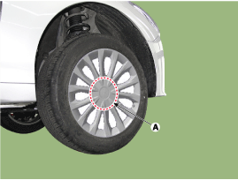
Remove the wheel cap(A).
|
| 3. |
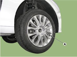
Remove the front wheel and tire (A) from front hub.
|
| 4. |
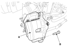
Loosen the guide rod bolt (B) and pivot the caliper (A) up out of the way.
|
| 5. |
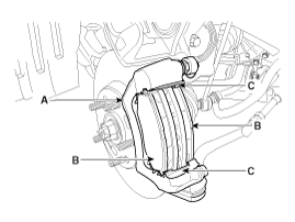
Replace pad shim, pad retainers (C) and brake pads (B) in the caliper bracket (A).
|
| 6. |
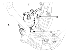
Loosen the hose eyebolt (C) and caliper mounting bolts (B), then remove the front caliper assembly (A).
|
| 7. |
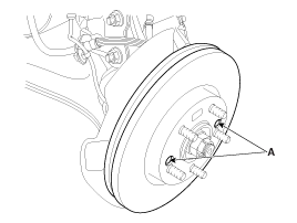
Remove the front brake disc by loosening the screws (A).
|
| Replacement |
| 1. |
Loosen the guide rod bolt (B) and pivot the caliper (A) up out of the way.
|
| 2. |
Replace pad shim (D), pad retainers (C) and brake pads (B) in the caliper bracket (A).
|
| 3. |
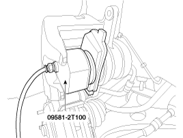
Use a SST (09581-2T100) when installing the brake caliper assembly.
|
| 4. |
Down the caliper body(A) then tighten the guide rod bolt(B).
|
| Inspection |
| 1. |
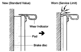
Check the brake pads for wear and fade. |
| 2. |
Check the brake disc for damage and cracks. |
| 3. |
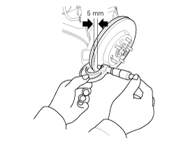
Remove all rust and contamination from the surface, and
measure the disc thickness at 8 points, at least, of same distance (5mm)
from the brake disc outer circle
|
| 4. |
If wear exceeds the limit, replace the discs and pad assembly left and right of the vehicle.
|
| 1. |
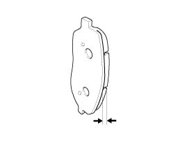
Check the pad wear. Measure the pad thickness and replace it, if it is less than the specified value.
|
| 1. |
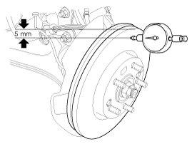
Place a dial gauge about 5mm (0.2 in.) from the outer circumference of the brake disc, and measure the runout of the disc.
|
| 2. |
If the runout of the brake disc exceeds the limit specification, replace the disc, and then measure the runout again. |
| 3. |
If the runout does not exceed the limit specification,
install the brake disc after turning it 180° and then check the runout
of the brake disc again. |
| 4. |
If the runout cannot be corrected by changing the position of the brake disc, replace the brake disc. |
| Installation |
| 1. |
Installation is the reverse of removal. |
| 2. |
Use a SST (09581-2T100) when installing the brake caliper assembly.
|
| 3. |
After installation, bleed the brake system.
(Refer to Brake System - "Brake System Bleeding")
(Refer to ABS - "ABS System Bleeding")
(Refer to ESP (Electronic Stability Program) System - "ESP System Bleeding") |
 Rear Disc Brake Components and Components Location
Components [General] 1. Guide rod bolt2. Bleed screw3. Caliper bracket4. Caliper body5. Inner pad shim6. Brake pad7. Pad retainer [EPB] 1...
Other information:
Hyundai Sonata LF 2014-2019 Service Manual: Starter Repair procedures
Removal 1. Disconnect the battery negative terminal. 2. Remove the battery tray. (Refer to Engine Electrical System - "Battery") 3. Remove the air duct and air cleaner assembly. (Refer to Engine Mechanical System - "Air Cleaner") 4...
Hyundai Sonata LF 2014-2019 Service Manual: Steering Angle Sensor Repair procedures
Adjustment Calibration (Setting up the zero angle) Steering Wheel Angle Sensor of a absolute angle type (CAN type) measures the angle under the standard of the zero angle set. Calibration must be performed as following cases. - Replacement of the Steering Wheel Angle Speed Sensor - Replacement or repair of the Steering column - Detection of DTC codes (C1260, C1261) - Replacement of the sensor cluster - Replacement of HECU Calibration procedure Perform wheel alignment and stand the steering wheel in a line within ±5°error...
Categories
- Manuals Home
- Hyundai Sonata Owners Manual
- Hyundai Sonata Service Manual
- Air Conditioning System
- ESP(Electronic Stability Program) System
- Engine Control System
- New on site
- Most important about car

