
Hyundai Sonata LF: Dual Clutch Transmission Control System / Components and Components Location
| Components |
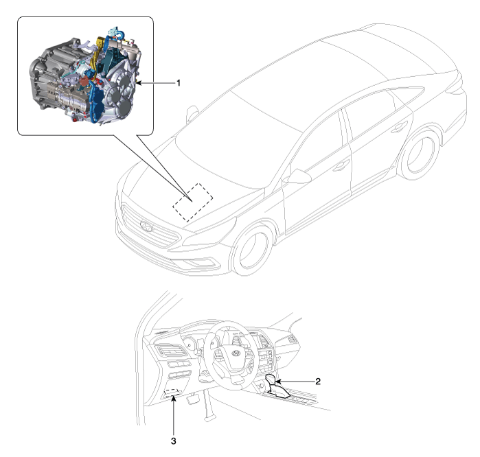
| 1. DCT (Dual Clutch Transmission) 2. Shift lever | 3. Data Link Connector (DLC) [16-Pin] |
 Description and Operation
Description The Dual Clutch Transmission (DCT) control system measures required data to identify the state of the control target and computes the appropriate compensation value if adjustment is necessary...
 DCT Control Module (TCM) Description and Operation
Description • Function The Transmission Control Module (TCM) is like the brain for the Dual Clutch Transmission (DCT). It receives information from various sensors for a wide range of transmission controls to provide an optimal driving environment for the driver...
Other information:
Hyundai Sonata LF 2014-2019 Service Manual: ETC (Electronic Throttle Control) System Specifications
Specification [Throttle Position Sensor (TPS)] Throttle angle(°)Output Voltage (V)TPS1TPS200.504.50100.964.05201.413.59301.873.14402.322.68502.782.23603.231.77703.691.32804.140.86904.600.41984.650.35C.T (0)0.504.50W.O.T (86)4.410.59 [ETC Motor] ItemSpecificationCoil Resistance (?)0...
Hyundai Sonata LF 2014-2019 Service Manual: Rail Pressure Sensor (RPS) Description and Operation
Description Rail Pressure Sensor (RPS) is installed on the delivery pipe and measures the instantaneous fuel pressure in the delivery pipe. The sensing element (Semiconductor element) built in the sensor converts the pressure to voltage signal...
Categories
- Manuals Home
- Hyundai Sonata Owners Manual
- Hyundai Sonata Service Manual
- Brake System
- Heating, Ventilation and Air Conditioning
- Steering System
- New on site
- Most important about car
