Hyundai Sonata LF: BCM (Body Control Module) / Components and Components Location
| Components |
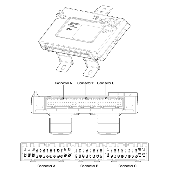
| No | Connector A | Connector B | Connector C |
| 1 | Room lamp_output | GND | Trunk release switch_input |
| 2 | Heated handle power_IGN 2 | - | Brake switch_input |
| 3 | heated handle_output | Auto light power_output | Fog lamp switch_input |
| 4 | - | Chassis CAN (Low) | Head lamp high switch_input |
| 5 | Safety power window enable_output | Chassis CAN (High) | Light switch_input |
| 6 | - | Wiper INT volume switch_input | Wiper switch_input |
| 7 | Wiper low relay_output | Body CAN (High) | Wiper low switch_input |
| 8 | Key hole illumination_output | Body CAN (Low) | Washer switch_input |
| 9 | - | Auto light GND_output | Heated handle NTC sensor_input |
| 10 | Wiper high relay_output | RPAS LIN Communication | IGN 1 |
| 11 | Courtesy lamp_output (Assist) | - | Battery (+) |
| 12 | Courtesy lamp_output (Driver) | - | Ground |
| 13 | Ground | - | heated handle switch_input |
| 14 | Ground | Diagnosis | Key IN switch_input |
| 15 | Pocket lamp_output | PAS_input (Option) | Rear defogger switch_input |
| 16 | - | AIR BAG signal_input | RPAS off switch_input |
| 17 | - | ? ? ? ? ? ? ? ? ? ? | Ket interlock switch_input |
| 18 | Security indicator_output | Sunroof open switch_input | |
| 19 | RPAS off switch indicator_output | Blade position_input | |
| 20 | Assist seat belt indicator_output | Auto light sensor_input | |
| 21 | AV Tail lamp_output | ACC | |
| 22 | - | IGN 2 | |
| 23 | Heated handle indicator_output | ? ? ? ? | |
| 24 | - | ||
| 25 | Key solenoid_output | ||
| 26 | AT solenoid_output |
 Specifications
Specifications ItemsSpecificationsRated voltageDC 12VOperating voltageDC 9 ~ 16VOperating temperature-22°F ~ 167°F (-30°C ~ 75°C)Dark currentSMK : 3mA / Keyless : 3...

Other information:
Hyundai Sonata LF 2014-2019 Service Manual: Special Service Tools
Special Service Tools Tool(Number and Name)IllustrationUse09200-3N000Engine support fixture(Beam)Removal and installation of the transaxle.Use this beam (SST No. : 09200-3N000) with the supporter (SST No. : 09200-2S000).?Permit operating with 09200-38001...
Hyundai Sonata LF 2014-2019 Service Manual: Instrument Cluster Description and Operation
Description Communication Network Diagram AbbreviationExpalnationACUAirbag Control UnitADMAssist Door ModuleB_CANBody Controller Area NetworkBCMBody Control ModuleBSDBlind Spot DetectionC_CANChassis Controller Area NetworkCLUCluster ModuleDATCDual Automatic Temp ControlDDMDriver Door ModuleESCElectronic Stability ProgramEMSEngine Management SystemLDWSLane Departure Warning SystemM_CANMulti media Controller Area NetworkMDPSMotor Driven Power SteeringP_CANPowertrain Controller Area NetworkPSMPower Seat ModuleSASSteering Angle SensorSJBSmart Junction BlockSMKSmart Key UnitSPASSmart Parking Assist SystemTCUTransmission Control UnitTPMSTire Pressure Monitoring SystemVDCVehicle Dynamic ControlTMUTelematics SystemABSAnti-lock Brake SystemSCCSmart Cruise Control Cluster Variant Coding As we have more options (ESC, MDPS, SCC, etc...
Categories
- Manuals Home
- Hyundai Sonata Owners Manual
- Hyundai Sonata Service Manual
- Brake System
- DCT (Dual Clutch Transmission) System
- Engine Mechanical System
- New on site
- Most important about car
