Hyundai Sonata LF: Audio / Antenna Repair procedures
Hyundai Sonata LF 2014-2019 Service Manual / Body Electrical System / Audio / Antenna Repair procedures
| Inspection |
Glass Antenna Test
| 1. |
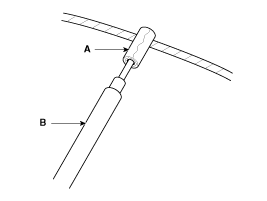
Wrap aluminum foil (A) around the tip of the tester probe (B) as shown.
|
| 2. |
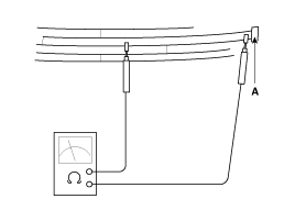
Touch one tester probe to the glass antenna terminal (A) and
move the other tester probe along the antenna wires to check that
continuity exists.
|
Glass Antenna Repair
To make an effective repair, the broken section must be no longer than one inch. |
| 1. |
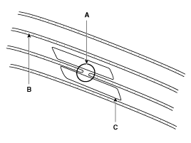
Lightly rub the area around the broken section (A) with fine steel wool, and then clean it with alcohol.
|
| 2. |
Carefully mask above and below the broken portion of the glass antenna wire (B) with cellophane tape (C). |
| 3. |
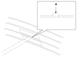
Using a small brush, apply a heavy coat of silver conductive
paint (A) extending about 1/8?on both sides of the break. Allow 30
minutes to dry.
|
| 4. |
Check for continuity in the repaired wire. |
| 5. |
Apply a second coat of paint in the same way. Let it dry three hours before removing the tape. |
Glass Antenna Circuit Inspection
| 1. |
Remove the rear pillar trim.
(Refer to Body - "Rear Pillar Trim") |
| 2. |
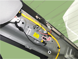
Disconnect the antenna amp power connector (A) from the glass antenna amp.
|
| 3. |
Turn the radio ON.
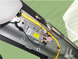
Measure the voltage between terminals of the antenna amp power connector (A) and body ground (B).
|
| 4. |
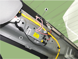
Check for radio antenna wire resistance between terminals of the antenna connector (A) and body ground (B).
|
| 5. |
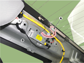
Check the grid lines for continuity. |
| 6. |
When a poor radio reception is not repaired through the above inspection methods, replace the amp.
If the radio reception is still poor, check the radio cable for short and radio head unit for failure. |
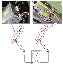
Antenna Cable
| 1. |
Check for continuity between the center poles of antenna cable.
|
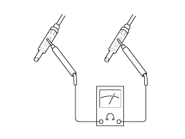
| 2. |
Check for continuity between the outer poles of antenna cable. There should be continuity.
|
| 3. |
If there is no continuity, replace the antenna cable. |
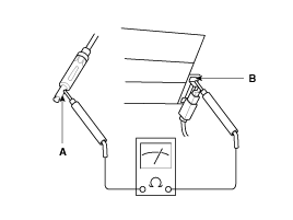
| 4. |
Check for continuity between the center pole (A) of antenna cable and terminal of glass antenna (B). There should be continuity.
|
| 5. |
If there is no continuity, replace the antenna amplifier. |
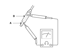
| 6. |
Check for continuity between the center pole (A) and outer pole (B) of antenna cable. There should be no continuity.
|
| 7. |
If there is continuity, replace the antenna cable. |
| Removal |
Roof Antenna
| 1. |
Disconnect the negative (-) battery terminal. |
| 2. |
Remove the roof trim.
(Refer to Body - "Roof Trim Assembly") |
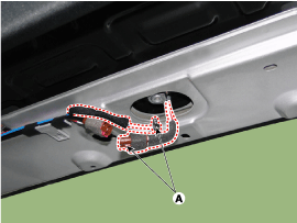
| 3. |
Disconnect the roof antenna connector (A).
|
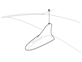
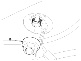
| 4. |
Remove the roof antenna (A) after loosening a nut (B).
|
| Installation |
Roof Anenna
| 1. |
Connect the roof antenna connectors. |
| 2. |
Install the roof trim assembly.
|
Other information:
Hyundai Sonata LF 2014-2019 Service Manual: Rear Body Body Repair
* These dimensions indicated in this figure are actual-measurement dimensions. [ Unit : mm (inch) ] Side outer panel rear cornerSide outer panel rear cornerSide outer panel rear cornerRear combination lamp mounting hole (O6)Rear bumper mounting hole (8...
Hyundai Sonata LF 2014-2019 Service Manual: Movable Glass Repair procedures
Replacement 1. Completely open the movable glass using the panorama sunroof switch. 2. Remove both sides of the decoration cover (A). 3. Completely close the movable glass using the panorama sunroof switch. 4. Adjust the height of the glass by slighty loosening the screws (A)...
Categories
- Manuals Home
- Hyundai Sonata Owners Manual
- Hyundai Sonata Service Manual
- Brake System
- ESP(Electronic Stability Program) System
- Intake And Exhaust System
- New on site
- Most important about car
Copyright В© 2025 www.hsonatalf.org

