
Hyundai Sonata LF: SRSCM / Schematic Diagrams
| Circuit Diagram (1) |
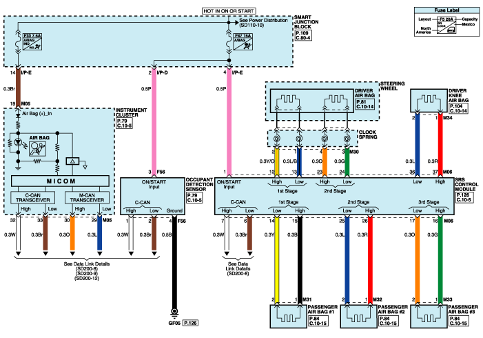
| Circuit Diagram (2) |
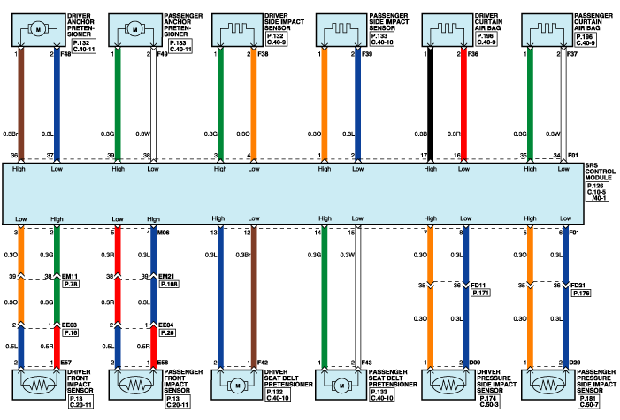
| Circuit Diagram (3) |
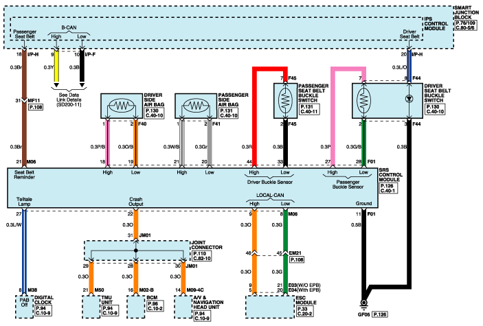
| SRSCM Connector Terminal |
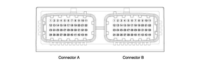
| Pin | Function (Connector A) | Pin | Function (Connector B) |
| A1 | IGN-1 | B1 | Side impact sensor front, Passenger-High (+) |
| A2 | Front impact sensor driver-High (+) | B2 | Side impact sensor front, Passenger-Low (-) |
| A3 | Front impact sensor driver-Low (-) | B3 | Side impact sensor front, Driver-High (+) |
| A4 | Front impact sensor passenger-High (+) | B4 | Side impact sensor front, Driver-Low (-) |
| A5 | Front impact sensor passenger-Low (-) | B5 | Pressure side impact sensor passenger-High (+) |
| A6 | C-CAN ACU to Vehicle-Low (-) | B6 | Pressure side impact sensor passenger-Low (-) |
| A7 | C-CAN ACU to Vehicle-High (+) | B7 | Pressure side impact sensor driver-High (+) |
| A8 | Local CAN IMU to ESC-Low (-) | B8 | Pressure side impact sensor driver-Low (-) |
| A9 | Local CAN IMU to ESC-High (+) | B9 | - |
| A10 | - | B10 | - |
| A11 | - | B11 | Ground |
| A12 | Driver airbag 1st stage-High (+) | B12 | Retractor pretensioner front, Driver-Low (-) |
| A13 | Driver airbag 1st stage-Low (-) | B13 | Retractor pretensioner front, Driver-High (+) |
| A14 | Passenger airbag 1st stage-Low (-) | B14 | Retractor pretensioner front, Passenger-High (+) |
| A15 | Passenger airbag 1st stage-High(+) | B15 | Retractor pretensioner front, Passenger-Low (-) |
| A16 | Passenger airbag active vent-High (+) | B16 | Curtain airbag driver-Low (-) |
| A17 | Passenger airbag active vent-Low (-) | B17 | Curtain airbag driver-High (+) |
| A18 | - | B18 | Side airbag front, driver-High (+) |
| A19 | - | B19 | Side airbag front, driver-Low (-) |
| A20 | - | B20 | Side airbag front, passenger-Low (-) |
| A21 | Seat belt reminder | B21 | Side airbag front, passenger-High (+) |
| A22 | Crash output | B22 | - |
| A23 | Driver airbag 2nd stage-High (+) | B23 | - |
| A24 | Driver airbag 2nd stage-Low (-) | B24 | - |
| A25 | Passenger airbag 2nd stage-Low (-) | B25 | - |
| A26 | Passenger airbag 2nd stage-High (+) | B26 | - |
| A27 | Passenger airbag OFF lamp (telltale lamp) | B27 | Seat belt buckle sensor front, Driver-High (+) |
| A28 | - | B28 | Seat belt buckle sensor front, Driver-Low(-) |
| A29 | - | B29 | - |
| A30 | - | B30 | - |
| A31 | - | B31 | - |
| A32 | - | B32 | - |
| A33 | - | B33 | Seat belt buckle sensor front, Passenger-Low (-) |
| A34 | - | B34 | Curtain airbag passenger-Low (-) |
| A35 | - | B35 | Curtain airbag passenger-High (+) |
| A36 | Knee airbag driver-Low (-) | B36 | Anchor pretensioner driver-High (+) |
| A37 | Knee airbag driver-High (+) | B37 | Anchor pretensioner driver-Low (-) |
| A38 | - | B38 | Anchor pretensioner passenger-Low (-) |
| A39 | - | B39 | Anchor pretensioner passenger-High (+) |
| A40 | - | B40 | - |
| A41 | - | B41 | - |
| A42 | - | B42 | - |
| A43 | - | B43 | - |
| A44 | - | B44 | Seat belt buckle sensor front, Passenger-High (-) |
 Seat Belt Buckle Switch (BS) Repair procedures
Removal 1. Disconnect the battery negative cable, and wait for at least three minutes before beginning work. 2. Remove the front seat assembly...

Other information:
Hyundai Sonata LF 2014-2019 Service Manual: Steering Angle Sensor Description and Operation
Description Steering Wheel Angle Sensor detects rotating direction of the vehicle. Rotating direction detected by the sensor is communicated with HECU as CAN signal involving information about the angle through CAN communication line. HECU detects speed of the steering wheel handling and the angle with this CAN signal...
Hyundai Sonata LF 2014-2019 Service Manual: Fuel Pressure Sensor (FPS) Schematic Diagrams
Circuit Diagram Fail-Safe Mode Item Fail-Safe Output Voltage (V) 12 If the fuel pressure sensor malfunctions, it enters fail safe mode. This means that the fuel pressure rises to match the increasing value of the current level and the pressure in the low pressure fuel line remains static despite the rising fuel pressure...
Categories
- Manuals Home
- Hyundai Sonata Owners Manual
- Hyundai Sonata Service Manual
- Driveshaft and axle
- Engine And Transmission Assembly
- Suspension System
- New on site
- Most important about car
