Hyundai Sonata LF: Seat Electrical / Lumber Support Units Repair procedures
Hyundai Sonata LF 2014-2019 Service Manual / Body Electrical System / Seat Electrical / Lumber Support Units Repair procedures
| Removal |
| 1. |
Disconnect the negative (-) battery terminal. |
| 2. |
Remove the front seat assembly.
(Refer to Body - "Front Seat Assembly") |
| 3. |
Remove the seat back.
(Refer to Body - "Front Seat Back Cover") |
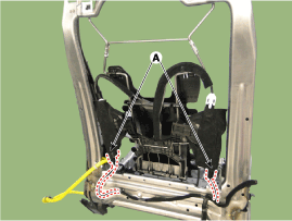
| 4. |
Disconnect the lumbar support motor connector (A).
|
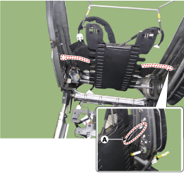
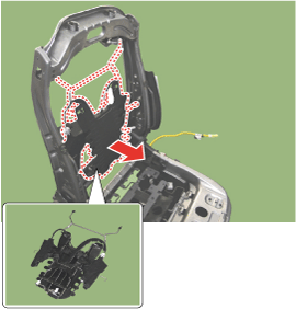
| 5. |
Remove the lumbar support assembly after disengaging mounting clip (A).
|
| Installation |
| 1. |
Install the lumbar support assembly. |
| 2. |
Install the seat back cover. |
| 3. |
Install the front seat assembly.
|

| Inspection |
Diagnosis with GDS
| 1. |
The body electrocal system can be quickly diagnosed failed parts with vehicle diagnostic system (GDS).
The diagnostic system (GDS) provides the following information.
|
| 2. |
Select the "Car Model" and the system to be checked in order to check the vehicle with the tester. |
| 3. |
Select the "Power Seat Module (PSM)" to check the power seat module (PSM). |
| 4. |
Select the "Current Data" menu to search the current state of the input/output data.
The input/output data for the sensors corresponding to the power seat module (PSM) can be checked. |
| 5. |
If you will check the power door lock operation forcefully, select "Actuation Test". |
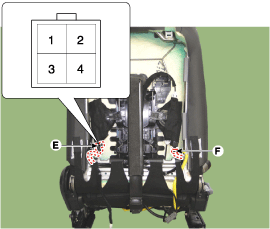
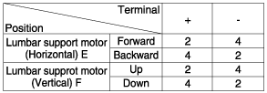
Lumbar Support Motor
| 1. |
Disconnect the connectors for each motor.
[Lumbar Support Motor]
|
| 2. |
With the battery connected directly to the motor terminals, check if the motors run smoothly. |
| 3. |
Reverse the connections and check that the motor turns in reverse. |
| 4. |
If there is an abnormality, replace the motors.
|

 Fuel Filler Door
Components and Components Location Component Location 1. Fuel filler door open switch2. Fuel filler door release actuator Fuel Filler Door Release Actuator Repair procedures Inspection 1...
Categories
- Manuals Home
- Hyundai Sonata Owners Manual
- Hyundai Sonata Service Manual
- Transmission Gear Oil Repair procedures
- General Information
- Repair procedures
- New on site
- Most important about car

Copyright © 2026 www.hsonatalf.org