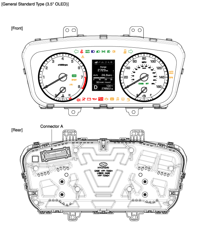
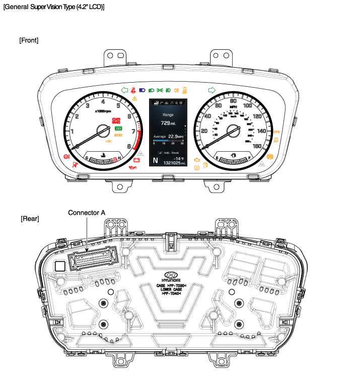
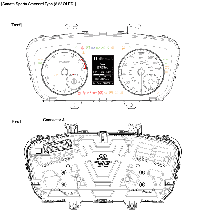
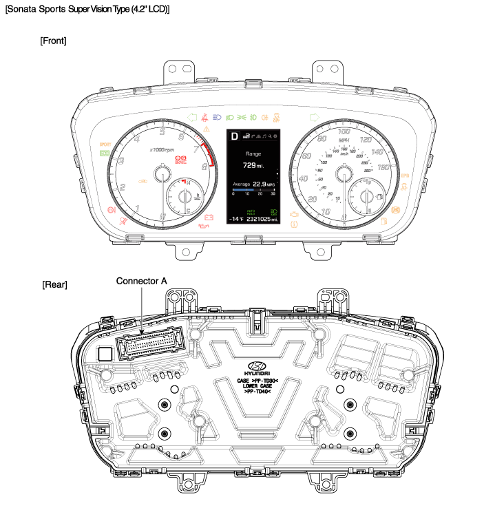
Hyundai Sonata LF: Indicators And Gauges / Instrument Cluster Components and Components Location
Hyundai Sonata LF 2014-2019 Service Manual / Body Electrical System / Indicators And Gauges / Instrument Cluster Components and Components Location
| Components |


Connector Pin Information
| No | Description | No | Description |
| 1 | - | 21 | Speaker (+) |
| 2 | Illumination (-) | 22 | Speaker (+) |
| 3 | Rheostat switch (Down)_Input | 23 | Immobilizer_Input |
| 4 | Rheostat switch (Up)_Input | 24 | AT ('P' Position) |
| 5 | - | 25 | AT ('R' Position) |
| 6 | Oil press switch_Input | 26 | AT ('N' Position) |
| 7 | Washer level (Low signal)_Input | 27 | AT ('D' Position) |
| 8 | Alternator_Input | 28 | AT ('S' Position) |
| 9 | LDWS_Input | 29 | Multimedia-CAN (Low) |
| 10 | Driver mode switch_Input | 30 | Multimedia-CAN (High) |
| 11 | Detent | 31 | - |
| 12 | Active ECO switch_Input | 32 | Chassis-CAN (High) |
| 13 | - | 33 | Chassis-CAN (Low) |
| 14 | Fuel sender (+)_Input | 34 | Trip switch 1 (+)_Input |
| 15 | - | 35 | Trip switch 2 (+)_Input |
| 16 | Fuel sender (-)_Input | 36 | Trip switch (-)_Input |
| 17 | Vehicle speed | 37 | GND |
| 18 | - | 38 | - |
| 19 | AIR BAG (+)_Input | 39 | IGN 1 |
| 20 | Tail lamp_Input | 40 | Battery (+) |
Categories
- Manuals Home
- Hyundai Sonata Owners Manual
- Hyundai Sonata Service Manual
- Brake System
- Engine Control / Fuel System
- Engine And Transmission Assembly
- New on site
- Most important about car
Copyright В© 2026 www.hsonatalf.org


