
Hyundai Sonata LF: Tires/Wheels / Tire Repair procedures
|

| Tire Wear |
| 1. |
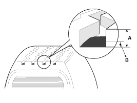
Measure the tread depth of the tires.
|
| 2. |
If the remaining tread depth (A) is less than the limit, replace the tire.
|
| Checking For Pull And Wander |
| 1. |
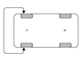
Rotate the front right and front left tires, and perform a road test in order to confirm vehicle stability.
|
| 2. |
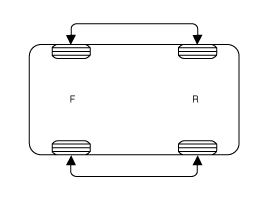
If the steering pulls to the opposite side, rotate the front and rear tires, and perform a road test again.
|
| 3. |
If the steering continues to pull to one side, rotate the front right and left tires again, and perform a road test.
|
| 4. |
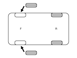
If the steering continues to pull to the opposite side, replace the front wheels with new ones.
|
| Removal |
| 1. |
Remove valve core and deflate the tire. |
| 2. |
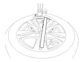
Remove the side of the tire bead area from the wheel using tire changing machine .
|

| 3. |
Rotate the wheel clockwise.
|

| Installation |
| 1. |
Apply tire soap or lubrication to the top and bottom tire beads.
|
| 2. |
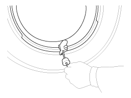
To fit the bottom bead, position the valve at the 5 o’clock position relative to the head on the tire changing machine.
|
| 3. |
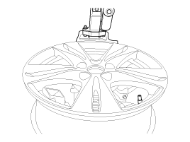
Place the tire on the rim so the bottom bead touches the
edge of the rim after the valve (6 o’clock). Rotate the rim clockwise,
and push down on the tire at the 3 o’clock position to fit bottom
bead.
|
| 4. |
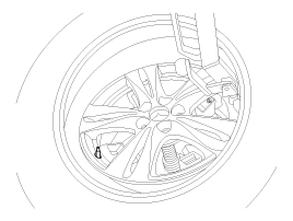
After bottom bead is on tire, rotate the rim until the valve
is at the 5 o’clock position relative to the head on the tire changing
machine. Push down on the tire at the 3 o’clock position and rotate
the rim clockwise to fit the top bead.
|
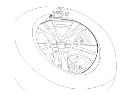
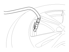
| 5. |
Inflate the tire until both beads seat.
|
 Tires/Wheels
..
 Wheel Repair procedures
Hub nut tightening sequence Tighten the hub nuts as follows. Tightening torque: 88.3 ~ 107.9N.m (9.0 ~ 11.0kgf.m, 65.1 ~ 79.6lb-ft) When using an impact gun, final tightening torque should be checked using a torque wrench...
Other information:
Hyundai Sonata LF 2014-2019 Service Manual: Alternator Schematic Diagrams
Circuit Diagram • COM signal - When controlling the voltage generated, the ECM sends the target voltage data to the alternator via a PWM signal.(High voltage: 4V or higher, low voltage: 2V or lower) • FR signal - The transistor activation signal inside the alternator monitors the voltage generated by the alternator to control the excitation current before it sends the FR signal to the ECM...
Hyundai Sonata LF 2014-2019 Service Manual: Engine Control Module (ECM) Schematic Diagrams
ECM Terminal And Input/Output signal ECM Terminal Function Connector [C500-A] Pin No.DescriptionConnected to1Injector (Cylinder #3) [High] control outputInjector (Cylinder #3)2Injector (Cylinder #4) [High] control outputInjector (Cylinder #4)3Injector (Cylinder #2) [Low] control outputInjector (Cylinder #2)4Electric Waste Gate Actuator (EWGA) DC Motor output (+)Electric Waste Gate Actuator (EWGA) 5Heated Oxygen Sensor (HO2S) [Bank 1/Sensor 1] heater control outputHeated Oxygen Sensor (HO2S) [Bank 1/Sensor 1]6-?7-8-?9Sensor ground Electric Waste Gate Actuator (EWGA) 10-?11-?12-13-?14Cooling fan relay [High] control outputCooling fan relay [High]15CVVT Oil Control Valve (OCV) [Bank 1/Exhaust] control outputCVVT Oil Control Valve (OCV) [Bank 1/Exhaust]16Injector (Cylinder #2) [High] control outputInjector (Cylinder #2)17Injector (Cylinder #1) [High] control outputInjector (Cylinder #1)18Injector (Cylinder #3) [Low] control outputInjector (Cylinder #3)19Electric Waste Gate Actuator (EWGA) DC Motor output (-) Electric Waste Gate Actuator (EWGA) 20Heated Oxygen Sensor (HO2S) [Bank 1/Sensor2] heater control outputHeated Oxygen Sensor (HO2S) [Bank 1/Sensor 2]21-?22-?23Engine Coolant Temperature Sensor (ECTS) signal inputEngine Coolant Temperature Sensor (ECTS)?24Sensor groundEngine Coolant Temperature Sensor (ECTS) 25-?26Fuel Tank Pressure Sensor (FTPS) signal inputFuel Tank Pressure Sensor (FTPS)27Fuel pump relay control output (NON-Smart key type)Fuel pump relayCanister Close Valve (CCV) control output (Smart key type)Canister Close Valve (CCV)28-?29-30-?31Ignition coil (Cylinder #3) control outputIgnition coil (Cylinder #3)32Ignition coil (Cylinder #1) control outputIgnition coil (Cylinder #1)33Injector (Cylinder #1) [Low] control outputInjector (Cylinder #1)34Fuel Pressure Control Valve (FPCV) [High] control outputFuel Pressure Control Valve (FPCV)35ETC motor [-] control outputETC motor36-?37Knock Sensor (KS) signal inputKnock Sensor (KS)38Sensor groundKnock Sensor (KS)39-40Brake Light switch signal inputBrake switch41-42-43-?44-?45CVVT Oil Control Valve (OCV) [Bank 1/Intake] control outputCVVT Oil Control Valve (OCV) [Bank 1/Intake]46Ignition coil (Cylinder #4) control outputIgnition coil (Cylinder #4)47Ignition coil (Cylinder #2) control outputIgnition coil (Cylinder #2)48Injector (Cylinder #4) [Low] control outputInjector (Cylinder #4)49Fuel Pressure Control Valve (FPCV) [Low] control outputFuel Pressure Control Valve (FPCV)50ETC motor [+] control outputETC motor51-?52Electric Waste Gate Actuator (EWGA) Feed beck signal Electric Waste Gate Actuator (EWGA) 53Brake Test switch signal inputBrake switch54-?55-56Electric load signal input [Defrost]Alternator57Alternator COM signal outputAlternator58Engine speed signal outputCluster59Cooling fan relay [Low] control outputCooling fan relay [Low] 60- Connector [C500-K] Pin No...
Categories
- Manuals Home
- Hyundai Sonata Owners Manual
- Hyundai Sonata Service Manual
- Brake System
- DCT (Dual Clutch Transmission) System
- Front Driveshaft Repair procedures
- New on site
- Most important about car
