Hyundai Sonata LF: Starting System / Starter Schematic Diagrams
Hyundai Sonata LF 2014-2019 Service Manual / Engine Electrical System / Starting System / Starter Schematic Diagrams
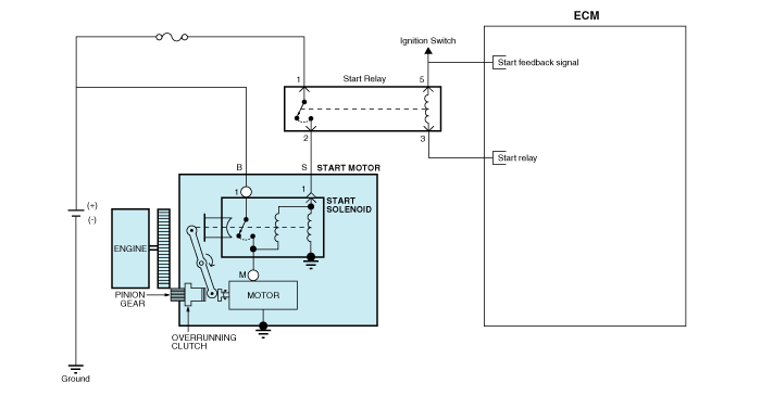
| Circuit Diagram |
 Starter Components and Components Location
Components 1. Screw2. Front housing3. Stop ring4. Stopper5. Overrunning clutch6. Lever7. Lever plate8. Lever packing9. Magnet switch assembly10. Armature assembly11...
 Starter Repair procedures
Removal 1. Disconnect the battery negative terminal. 2. Remove the battery tray. (Refer to Engine Electrical System - "Battery") 3. Remove the air duct and air cleaner assembly...
Other information:
Hyundai Sonata LF 2014-2019 Service Manual: Filler-Neck Assembly Repair procedures
Removal 1. Turn the ignition seitch OFF and disconnect the battery negative (-) cable. 2. Open the fuel filler door and then remove the filler-neck installation screw (A). 3. Lift the vehicle. 4. Remove the rear-LH wheel, tire, and the inner wheel house...
Hyundai Sonata LF 2014-2019 Service Manual: Inhibitor Switch Components and Components Location
C..
Categories
- Manuals Home
- Hyundai Sonata Owners Manual
- Hyundai Sonata Service Manual
- Heating, Ventilation and Air Conditioning
- Brake System
- Engine Control System
- New on site
- Most important about car

Copyright © 2026 www.hsonatalf.org