Hyundai Sonata LF: Cruise Control System / Cruise Control Switch Schematic Diagrams
| Circuit Diagram |
 Troubleshooting
Trouble Symptom Charts Trouble Symptom 1 Trouble Symptom 2 Trouble symptomProbable causeRemedyThe set vehicle speed varies greatly upward or downward"Surging" (repeated alternating acceleration and deceleration) occurs after settingMalfunction of the vehicle speed sensor circuitRepair the vehicle speed sensor system, or replace the partMalfunction of ECMCheck input and output signals at ECM Trouble Symptom 3 Trouble symptomProbable causeRemedyThe CC system is not canceled when the brake pedal is depressedDamaged or disconnected wiring of the brake pedal switchRepair the harness or replace the brake pedal switchMalfunction of the ECM signalsCheck input and output signals at ECM Trouble Symptom 4 Trouble symptomProbable causeRemedyThe CC system is not canceled when the shift lever is moved to the "N" position (It is canceled, however, when the brake pedal is depressed)Damaged or disconnected wiring of inhibitor switch input circuitRepair the harness or repair or replace the inhibitor switchImproper adjustment of inhibitor switchMalfunction of the ECM signalsCheck input and output signals at ECM Trouble Symptom 5 Trouble symptomProbable causeRemedyCannot decelerate (coast) by using the "SET/–" switchTemporary damaged or disconnected wiring of "SET/–" switch input circuitRepair the harness or replace the "SET/–" switchMalfunction of the ECM signalsCheck input and output signals at ECM Trouble Symptom 6 Trouble symptomProbable causeRemedyCannot accelerate or resume speed by using the "RES/+" switchDamaged or disconnected wiring, or short circuit, or "RES/+" switch input circuitRepair the harness or replace the "RES/+" switchMalfunction of the ECM signalsCheck input and output signals at ECM Trouble Symptom 7 Trouble symptomProbable causeRemedyCC system can be set while driving at a vehicle speed of less than 40km/h (25mph), or there is no automatic cancellation at that speedMalfunction of the vehicle-speed sensor circuitRepair the vehicle speed sensor system, or replace the partMalfunction of the ECM signalsCheck input and output signals at ECM Trouble Symptom 8 Trouble symptomProbable causeRemedyThe cruise main switch indicator lamp does not illuminate (But CC system is normal)Damaged or disconnected bulb of cruise main switch indicator lampRepair the harness or replace the part...
 Cruise Control Switch Repair procedures
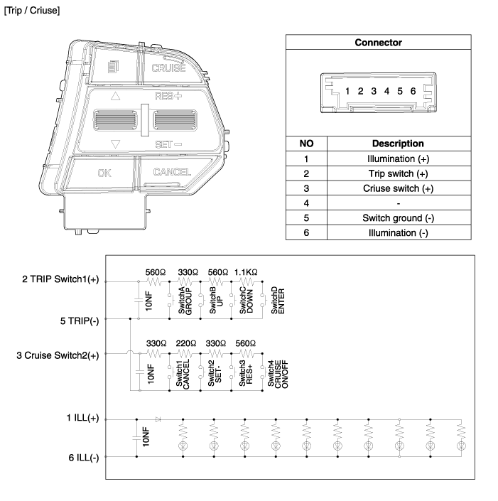
Inspection [Measuring Resistance] 1. Disconnect the cruise control switch connector from the control switch. 2. Measure resistance between terminals on the control switch when each function switch is ON (switch is depressed)...
Other information:
Hyundai Sonata LF 2014-2019 Service Manual: Fuel Filler Door
Components and Components Location Component Location 1. Fuel filler door Repair procedures Replacement • Put on gloves to protect your hands. • When prying with a flat-tip screwdriver or use a prying trim tool, wrap it with protective tape, and apply protective tape around the related parts, to prevent damage...
Hyundai Sonata LF 2014-2019 Service Manual: Specifications
Specifications Front Suspension ItemSpecificationSuspension typeMac Pherson StrutShock absorberTypeGasHPD (High Performance Damper) Rear Suspension ItemSpecificationSuspension typeMulti linkShock absorberTypeGasHPD (High Performance Damper) Wheel & Tire ItemSpecificationWheelalumium6...
Categories
- Manuals Home
- Hyundai Sonata Owners Manual
- Hyundai Sonata Service Manual
- Transmission Gear Oil General Information
- Cylinder Head Cover Repair procedures
- Front Driveshaft Repair procedures
- New on site
- Most important about car
