
Hyundai Sonata LF: ESP(Electronic Stability Program) System / Steering Angle Sensor Repair procedures
| Adjustment |
| - |
Replacement of the Steering Wheel Angle Speed Sensor |
| - |
Replacement or repair of the Steering column |
| - |
Detection of DTC codes (C1260, C1261) |
| - |
Replacement of the sensor cluster |
| - |
Replacement of HECU |
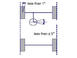
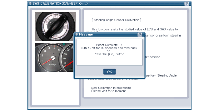
| 1. |
Connect the GDS. (CAN line or OBD connector) |
| 2. |
Turn ignition switch on. |
| 3. |
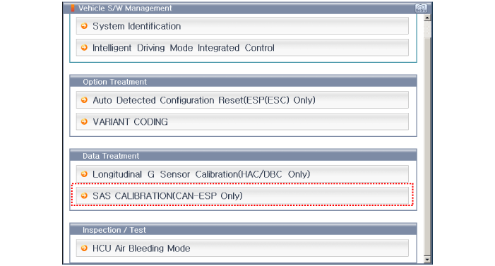
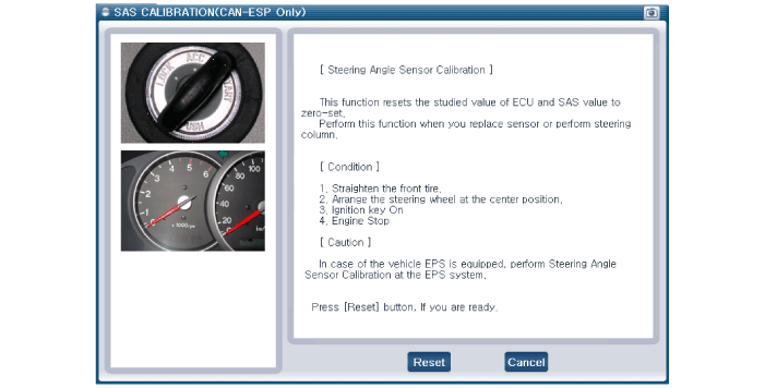
Press calibration button of the Steering Wheel Angle Sensor. |
| 4. |
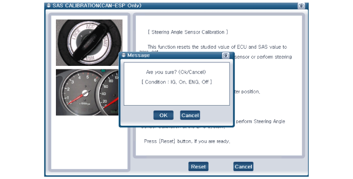
SAS calibration procedure is performed.
(Calibration records, DTC codes erasure)
|

 ESP Control Unit Components and Components Location
Components 1. Front - left tube2. Rear - right tube3. Rear - left tube4. Front - right tube5. MC26. MC17. EPS control module(HECU) connector8. EPS control module(HECU)9...
Other information:
Hyundai Sonata LF 2014-2019 Service Manual: Rear Glass Defogger
Components and Components Location Component Location 1. Rear glass defogger relay Smart Junction Block (SJB)2. Rear glass defogger switch3. Rear glass defogger Rear Glass Defogger Printed Heater Repair procedures Inspection Wrap tin foil around the end of the voltmeter test lead to prevent damaging the heater line...
Hyundai Sonata LF 2014-2019 Service Manual: Crankcase Emission Control System
Schematic Diagrams Schematic Diagram Repair procedures Inspection 1. After disconnecting the vapor hose from the PCV valve, remove the PCV valve. 2. Reconnect the PCV valve to the vapor hose. 3. Inspect the PCV vlave operation. (1) Run the engine at idle...
Categories
- Manuals Home
- Hyundai Sonata Owners Manual
- Hyundai Sonata Service Manual
- Front Driveshaft Repair procedures
- Components and Components Location
- Heating, Ventilation and Air Conditioning
- New on site
- Most important about car
