
Hyundai Sonata LF: Air Conditioning System / In-car Sensor Repair procedures
| Diagnosis With GDS |
| 1. |
The heating, ventilation and air conditioning can be quickly diagnosed failed parts with vehicle diagnostic system (GDS).
? The diagnostic system (GDS) provides the following information.
(1) Self diagnosis: Checking the failure code (DTC) and display.
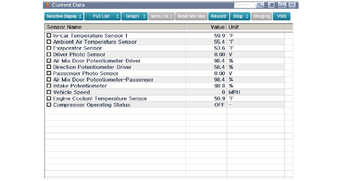
(2) Current data: Checking the system input/output data state.
(3) Actuation test: Checking the system operation condition.
(4) Additional function: Other controlling such as he system option and zero point adjustment. |
| 2. |
Select the 'Car model' and the system to be checked in order to check the vehicle with the tester. |
| 3. |
Select the 'Current data' menu to search the current state of the input/output data.
The input/output data for the sensors corresponding to the In-car Sensor can be checked.
|
 In-car Sensor Description and Operation
Description The sensor contains a thermistor which measures the temperature of the inside. The signal decided by the resistance value which changes in accordance with perceived inside temperature, is delivered to heater control unit and according to this signal the control unit regulates incar temperature to intended value...
 Photo Sensor Description and Operation
Description The photo sensor is located at the center of the defrost nozzles. The photo sensor contains a photovoltaic (sensitive to sunlight) diode...
Other information:
Hyundai Sonata LF 2014-2019 Service Manual: Air Cleaner Components and Components Location
C..
Hyundai Sonata LF 2014-2019 Service Manual: Rear Door Window Glass Repair procedures
Replacement 1. Pull down rear door window glass by pressing the power window glass switch. 2. Remove the rear door trim. (Refer to Rear Door - "Rear Door Trim") 3. Remove the rear door belt outside weatherstrip (A). 4. After loosening the mounting screws, then remove the rear door delta garnish (A)...
Categories
- Manuals Home
- Hyundai Sonata Owners Manual
- Hyundai Sonata Service Manual
- Cooling System
- Body Electrical System
- Engine Electrical System
- New on site
- Most important about car
